


Manual PCI-DA12-8/16
16
Restrict-Output-Voltage limits the output of all DAC channels and is active at power-up. Since the pre-
load register is not cleared upon power-up, but left at an undefined value, known values must be written
to the preload registers before using a "Clear Restrict-Output-Voltage" command. Those written values
will then be output to the connector when a "Clear Restrict-Output-Voltage" command is issued by a read
of Base AF.
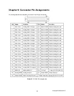
Address
Write *
Read
Base + 0
DAC 0 Low Byte
Place card in Simultaneous Mode without updating outputs.
Base + 1
DAC 0 High Byte
Base + 2
DAC 1 Low Byte
Release card from Simultaneous Mode without updating outputs.
Base + 3
DAC 1 High Byte
Enable Interrupts
Base + 4
DAC 2 Low Byte
Disable Interrupts
Base + 5
DAC 2 High Byte
Enable Timer-Initiated DAC Update
Base + 6
DAC 3 Low Byte
Disable Timer-Initiated DAC Update
Base + 7
DAC 3 High Byte
Base + 8
DAC 4 Low Byte
Update all outputs and place card in Simultaneous Mode.
Base + 9
DAC 4 High Byte
Base + A
DAC 5 Low Byte
Update all outputs and release card from Simultaneous Mode.
Base + B
DAC 5 High Byte
Base + C
DAC 6 Low Byte
Clear IRQ
Base + D
DAC 6 High Byte
Base + E
DAC 7 Low Byte
Restrict-Output-Voltage (Limits outputs to 15% of full scale range).
Base + F
DAC 7 High Byte
Clear Restrict-Output-Voltage (Allows full operating output voltage).
Base + 10
DAC 8 Low Byte
Base + 11
DAC 8 High Byte
Base + 12
DAC 9 Low Byte
Base + 13
DAC 9 High Byte
Base + 14
DAC 10 Low Byte
Base + 15
DAC 10 High Byte
Base + 16
DAC 11 Low Byte
Base + 17
DAC 11 High Byte
Base + 18
DAC 12 Low Byte
Base + 19
DAC 12 High Byte
Base + 1A
DAC 13 Low Byte
Base + 1B
DAC 13 High Byte
Base + 1C
DAC 14 Low Byte
Base + 1D
DAC 14 High Byte
Base + 1E
DAC 15 Low Byte
Base + 1F
DAC 15 High Byte
*
Although it is possible to write the low and high bytes separately as shown above, it is much easier to write both bytes with a
single OUT DX, AX instruction. In that case, only even addresses are written.
Table 5-1:
Register Map


