background image


11 


Installation 

1.  Attach the illuminator mount to pan/tilt unit, wall or camera housing. Using 

stainless steel fixings suitable for the relevant application. 

2.  Connect the lamp to a suitable (SELV) low voltage supply. Ensure that the 

polarity is correct. 

3.  Commission the mains supply, camera and monitoring equipment. 
4.  Select the diffuser angle sheet required from the scope of delivery (if required). 

To position the required diffuser sheet, insert the tool included in the slot at the 
bottom of the cover and prise upwards slowly. Repeat at opposite end and 
carefully remove cover. Remove backing sheet from the two adhesive discs 
and secure required diffuser in position. Finally firmly clip the lens cover back 
into place. 

5.  Adjust the pan angle of the illuminator to match the camera field of view. 
6.  Adjust the vertical alignment by loosening the side bolts (one on each side of 

the main body) to maximise the results. 

7.  SLOWLY and GRADUALLY tilt the lamp upwards until the for part of the 

required field of view is illuminated correctly on the monitor. 

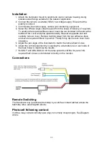
Connections 


Remote Switching 

The Illuminator may be activated remotely by a volt-free contact latched across the 
telemetry wires (see Diagram above). 

Photocell following contact 

Volt-free relay contact-normally open (day) to normally closed (night). See Diagram 
above. 


Содержание TVAC71070

Страница 1: ...Sprache F r k nftige Verwendung aufbewahren This user manual contains important information for installation and operation This should be also noted when this product is passed on to a third party Th...

Страница 2: ...zelle 6 Fotozelle Empfindlichkeit 6 Deaktivierung der Fotozelle 6 Probleml sung 7 Sicherheitshinweise 8 CONTENT Declaration of conformity 9 Features 10 Specification 10 Important information 10 Instal...

Страница 3: ...linie 2014 30 EU Nieder Spannungsrichtlinie 2014 35 EU RoHS Richtlinie 2011 65 EU Die vollst ndige EU Konformit tserkl rung kann unter folgender Adresse bezogen werden ABUS Security Center GmbH Co KG...

Страница 4: ...R Licht reflektierende Objekte im Blickfeld reduzieren die IR Reichweite bzw bedingen ein zu dunkles Videobild Ferner k nnen reflektierende Objekte in direkter Kameran he Dachrinne Wand st rende Refle...

Страница 5: ...langsam nach oben Wiederholen Sie dies am anderen Ende und entfernen Sie vorsichtig die Abdeckung Entfernen Sie die Schutzfolie von den beiden Klebescheiben und legen Sie die gew hlte Diffusor Linse...

Страница 6: ...onditions The unit is factory set at approximately 30 Lux On and 70 Lux Off but can be adjusted Fotozelle Empfindlichkeit Um die Empfindlichkeit der Fotozelle einzustellen entfernen Sie zuerst die Ver...

Страница 7: ...das ve rote Kabel von der Stromversorgung abziehen und ein Multimeter auf 10 A eingestellt an den Strahler anschlie en Ein Kabel des Multimeters gemeinsam COM ein anderes Kabel in die 10 A Buchse des...

Страница 8: ...in einem Abstand von weniger als 1 m nicht zu erwarten ist Die Lichtquelle dieses Strahlers ist nicht austauschbar Wenn die Lichtquelle das Ende ihrer Lebensdauer erreicht sollte der gesamte Illumina...

Страница 9: ...product EMC Directive 2014 30 EU Low Voltage Directive 2014 35 EU RoHS Directive 2011 65 EU The full EU declaration of conformity can be obtained from the following address ABUS Security Center GmbH...

Страница 10: ...field of view the IR range will be reduced and or the video image will be too dark Reflective objects in the immediate vicinity of the camera e g roof gutter or wall may also result in the reflection...

Страница 11: ...refully remove cover Remove backing sheet from the two adhesive discs and secure required diffuser in position Finally firmly clip the lens cover back into place 5 Adjust the pan angle of the illumina...

Страница 12: ...o void on off switching in marginal conditions The unit is factory set at approximately 30 Lux On and 70 Lux Off but can be adjusted Photocell Sensitivity To adjust the photocell sensitivity first rem...

Страница 13: ...ight and set correctly Check model number to performance specification to ensure required distance is achievable Step 4 Call for further assistance If the lamp is still not delivering the required per...

Страница 14: ...richt dem technischen Stand bei Drucklegung nderung in Technik und Ausstattung vorbehalten Imprint These operating instructions are published by ABUS Security Center GmbH Co KG Linker Kreuthweg 5 8644...

Отзывы: