


19
3. Connections and functions
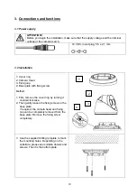
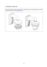
3.1 Power supply
ATTENTION!
Before you begin the installation, make sure that the supply voltage and the nominal
voltage of the camera match.
12 VDC, round plug, 5,5 x 2,1 mm
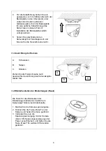
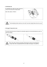
3.2 Installation
1: Cover ring
2: Camera Head
3: Fixing cap
4: Base plate with fixing screw
Method:
1. First, remove the cover ring by turning it
counterclockwise.
2. Then gently loosen the fixing screw on the
base plate.
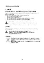
If required, the camera head and fixing
cap can be completely removed from the
base plate. Remove the fixing screw
completely.
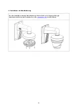
3 Use the supplied drilling template to mark
the mounting holes. Depending on the
substrate, please use suitable dowels and
screws. Then fix the bottom plate.
1
2
3
4


