background image

Introduction 

The Smart-Vue User Interface (UI) for the UC-3 HTLV Control System 
displays the information necessary to operate and diagnose the Heating 
and Ventilating Unit. 

This is connected to the controller via a CAT-5E cable with a maximum 
length of 600 feet. 

HMI Screen Information 

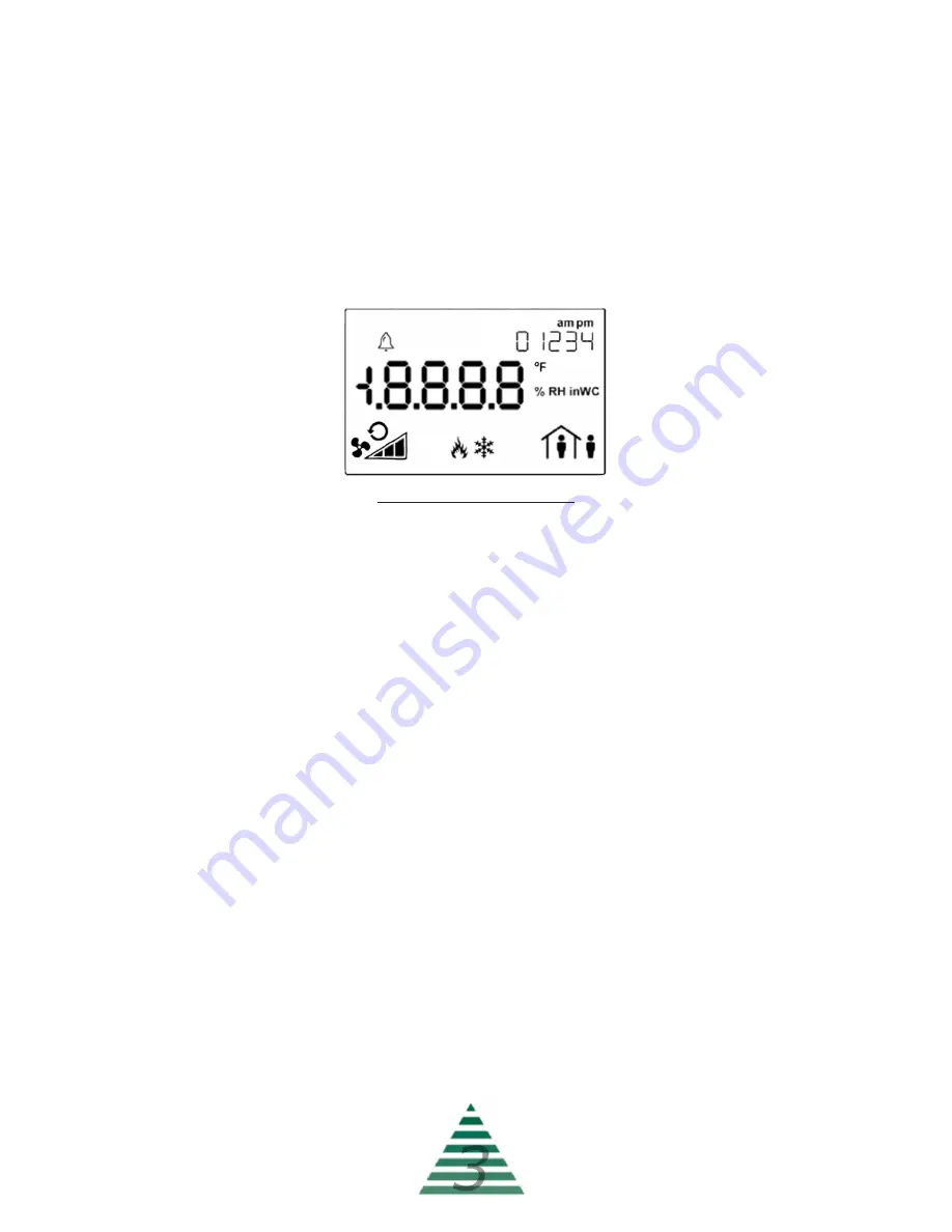
At the top left corner of the display there is a bell symbol. This is the system 
alarm indicator. If an alarm is present in the unit this indicator will blink. If no 
alarm is present this indicator will not be visible.At the top right of the 
display is instructions for turning the unit on/o

 as well as menu/sub-menu 

options names.  When navigating the menu, the menu title will be displayed 
here. Across the center of the display is the data with the units of measure. 
The system is capable of displaying up to 4 decimal places. At the bottom 
left is the fan status. In the bottom center is the mode of operation and at 
the bottom right is the occupancy status.

Three buttons are available for operation (see cover page). The center 
button allows you to access the menu and scroll through the menu items. 
The up/down buttons are used to change values. 

Operation 

The system displays the current Space Temperature when idle. The menu 
is separated into sub-menus for ease of use, and only the options the unit 
is equipped with will be displayed. When navigating the menu blinking 
items are set points that can be changed, while non-blinking items are 
status objects which can be viewed only. 

010622 

Содержание UC-3

Страница 1: ...UC 3 User Guide 2022 AbsolutAire Inc 010622 HTLV ...

Страница 2: ...signs AbsolutAire often builds equipment with special features as requested by the customer This manual only covers standard features and does not include any changes made for special feature requests by the customer 010622 ...

Страница 3: ...Sensor Alarm Display 4 A Note About Custom Designs 1 Introduction 3 Operation 3 Schedule 5 Menu Tree 7 Main Display 7 Quick Access 7 Set Points 7 Status 7 Schedule 8 Alarms 9 Config 10 Advanced Menu 10 Network Integration 11 Tables Network Points List 12 010622 ...

Страница 4: ...he menu the menu title will be displayed here Across the center of the display is the data with the units of measure The system is capable of displaying up to 4 decimal places At the bottom left is the fan status In the bottom center is the mode of operation and at the bottom right is the occupancy status Three buttons are available for operation see cover page The center button allows you to acce...

Страница 5: ...int Again use the up down arrow buttons to make your entry and press menu when finished Continue scrolling through the Set Points sub menu until all of your desired settings are completed When scrolling the menu and you see the option BACK in the top right pressing the up arrow will take you to the previous menu Scrolling through the STATUS sub menu will allow you to view the status of all of the ...

Страница 6: ...tatus is indicated by the occupancy icon in the lower right corner of the HMI screen A steady icon indicates the system is following the standard 7 day schedule while a blinking icon indicates the system is following a day programmed as a special event To program the 7 day schedule press the menu button until SCHEDULE appears in the top right of the display Press the up arrow to enter the schedule...

Страница 7: ... and day set to 0 will leave that event un programmed The first option will be the EVENT NUMBER Select the event desired event number 1 5 and press menu to navigate to EVENT MONTH Select the desired month 1 12 and press menu to confirm Press menu to navigate to EVENT DAY Select the desired day of the month 1 28 29 30 31 as allowed and press menu to confirm Press menu to navigate to OCC HOUR Select...

Страница 8: ... Set Point AV51 R W Occupied Heat Set Point Unoc Set Point AV52 R W Unoccupied Heat Set Point only available if the unit has scheduling as an option Burner Reset MSV54 R W Burner reset command for use during a burner lockout alarm This is an on _on_ toggle selectable via the up arrow button Status Space Temp AV33 R Current space temperature at the User Interface or remote space temperature sensor ...

Страница 9: ...inute to be programmed This is the minute of the hour the unit will assume unoccupied status Special Events Event Number The schedule supports up to five special events This is the event number to be programmed Event Month Month of the year the special event is in Event Day Day of the month the special event is on Occ Hour Occupied hour for the special event This is the hour in 24 hour format that...

Страница 10: ...inutes Check the burner for proper operation Dirty Filter MSV13 R Dirty filter indication only available if the unit has dirty filter monitoring as an option Motor Alarm MSV11 R Motor not responding alarm status This indicates the unit was enabled and the supply fan motor failed to start within two minutes Check VFD or overload as available OA damper limit switch and wiring and power Burner Respon...

Страница 11: ... R W The units minimum allowable discharge temperature Max Discharge AV55 R W The units maximum allowable discharge temperature Low Temp Set Pt AV56 R W If the unit discharges air below this temperature set point for Low Temp Time minutes it will shut down and close the isolation dampers Only available if LTL is available Low Temp Minutes AV57 R W The time delay in minutes for the Low Temp Alarm O...

Страница 12: ...ncremented MAC addresses The dip switches are numbered 1 through 8 with 1 being the LSB The numbering is standard binary format switches 1 and 3 ON equals an address of 5 The Network Instance Number device instance is automatically configured based on the MAC Address setting The network instance number will always be 3640 MAC Address For example if the MAC address is set to 25 the network instance...

Страница 13: ...010622 ...

Страница 14: ... This page intentionally left blank for notes 010622 ...

Отзывы: