


18. Reset
MC97F6108A User’s manual
190
18
Reset
Table 27 shows hardware setting values of main peripherals.
Table 27. Hardware Setting Values in Reset State
On Chip Hardware
Initial Value
Program Counter (PC)
0000h
Accumulator
00h
Stack Pointer (SP)
07h
Peripheral Clock
On
Control Register
Refer to the Peripheral Registers
MC97F6108A has six types of reset sources as shown in the followings:
External RESETB (In the case of RSTEN = '1')
Power ON RESET (POR)
WDT Overflow Reset (In the case of WDTEN = `1`)
BOD Reset
(In the case of BODLS ≠ `000 `)
Low Voltage Reset
OCD2 Reset
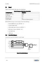
18.1
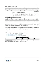
Reset block diagram
In this section, reset unit is described in a block diagram.
WDT RST
WDT RSTEN
Ext RESET
RSTENA
RESET Noise
Canceller
BOD_OUT
BOD Enable
RESET Noise
Canceller
POR RST
S Q
R
Internal
Reset
IFBIT
(BIT Overflow)
LVD RST
Figure 87. Reset Block Diagram