


MC97F6108A User’s manual
15. USART
155
15.8.4
Disabling receiver
In contrast to Transmitter, disabling the Receiver by clearing RXE bit makes the Receiver inactive
immediately. When the Receiver is disabled the Receiver flushes the receive buffer and the remaining
data in the buffer is all reset. Function of USART is not overridden on the RXD pin, so the RXD pin
becomes normal GPIO or primary function pin.
15.8.5
Asynchronous data reception
To receive asynchronous data frame, USART includes a clock and data recovery unit. Clock Recovery
logic is used for synchronizing the internally generated baud rate clock to the incoming asynchronous
serial frame on the RXD pin.
Data recovery logic samples incoming bits and low pass filters them, and this removes the noise of
RXD pin.
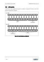
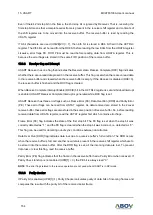
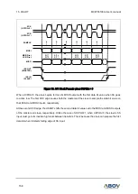
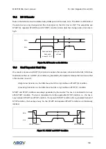
Figure 70 describes sampling process of the start bit of an incoming frame. The sampling rate is 16
times the baud rate for normal mode, and 8 times the baud rate for Double Speed mode (U2X=1). The
horizontal arrows show the synchronization variation due to the asynchronous sampling process. Note
that larger time variation is shown when using the Double Speed mode.
Figure 70. Start Bit Sampling
When Receiver is enabled (RXE=1), the clock recovery logic tries to find a high to low transition on the
RXD2 line, which is a start bit condition. After detecting the high to low transition on RXD line, the clock
recovery logic uses the samples 8, 9, and 10 for Normal mode, and the samples 4, 5, and 6 for Double
Speed mode to decide if a valid start bit is received. If more than 2 samples have logical low level, it is
considered that a valid start bit is detected and the internally generated clock is synchronized to the
incoming data frame. And the data recovery can begin. The synchronization process is repeated for
each start bit.
RxD2
0
0
1
2
3
4
5
6
7
8
9
10
11
12
13 14
15
16
1
2
3
IDLE
BIT0
START
0
1
2
3
4
5
6
7
8
1
2
Sample
(U2X = 0)
Sample
(U2X = 1)