


MC80F0304/08/16
52
November 4, 2011 Ver 2.12
n addition, see Figure 10-3 for the layout of the crystal.
Figure 10-3 Layout of Oscillator PCB circuit
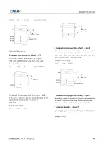
To drive the device from an external clock source, Xout should
be left unconnected while Xin is driven as shown in Figure 10-4
. There are no requirements on the duty cycle of the external clock
signal, since the input to the internal clocking circuitry is through
a divide-by-two flip-flop, but minimum and maximum high and
low times specified on the data sheet must be observed.
Oscillation circuit is designed to be used either with a ceramic
resonator or crystal oscillator. Since each crystal and ceramic res-
onator have their own characteristics, the user should consult the
crystal manufacturer for appropriate values of external compo-
nents.
Figure 10-4 External Clock Connections
In addition, the MC80F0304/0308/0316 has an ability for the ex-
ternal RC oscillated operation. It offers additional cost savings
for
timing insensitive applications
. The RC oscillator frequency
is a function of the supply voltage, the external resistor (R
EXT
)
and capacitor (C
EXT
) values, and the operating temperature.
The user needs to take into account variation due to tolerance of
external R and C components used.
Figure 10-1 shows how the RC combination is connected to the
MC80F0304/0308/0316. External capacitor (C
EXT
) can be omit-
ted for more cost saving. However, the characteristics of external
R only oscillation are more variable than external RC oscillation.
Figure 10-1 RC Oscillator Connections
Figure 10-2 R Oscillator Connections
To use the RC oscillation , the CLK option of the configuration
bits (20FF
H
) should be set to “EXRC or EXRCXO”.
The oscillator frequency, divided by 4, is output from the Xout
pin, and can be used for test purpose or to synchronize other logic.
In addition to external crystal/resonator and external RC/R oscil-
lation, the MC80F0304/0308/0316 provides the internal 4MHz or
2MHz oscillation. The internal 4MHz/2MHz oscillation needs no
external parts.
To use the internal 4MHz/2MHz oscillation, the CLK option of
the configuration bits should be set to “IN4MCLK”,
“IN2MCLK”, “IN4MCLKXO” or “IN2MCLKXO”. For detail
description on the configuration bits, refer to "23.. DEVICE
CONFIGURATION AREA" on page 116
X
OUT
X
IN
Xout
Xin
Vss
OPEN
External
Clock
Source
X
OUT
X
IN
Vdd
C
EXT
f
XIN
÷
4
R
EXT
Cint
≈
6pF
X
OUT
X
IN
V
DD
f
XIN
÷
4
R
EXT
C
INT
≈
6pF