A96G140/A96G148/A96A148 User’s manual
7. Interrupt controller
73
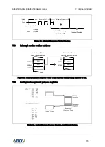
Figure 22. Interrupt Response Timing Diagram
7.8
Interrupt service routine address
Figure 23. Correspondence between Vector Table Address and the Entry Address of ISR
7.9
Saving/restore general purpose registers
Figure 24. Saving/Restore Process Diagram and Sample Source
Interrupt
latched
Interrupt
goes
active
System
Clock
Max. 4 Machine Cycle
4 Machine Cycle
Interrupt Processing
: LCALL & LJMP
Interrupt Routine
0EH
2EH
0125H
0126H
Basic Interval Timer
Service Routine Address
Basic Interval Timer
Vector Table Address
00B3H
00B4H
02H
25H
01H
00B5H

