background image


EN - 22

BAL.0533.0 • 2019-11-15

9 Maintenance and cleaning

FEC

9.4.3 Replace the exhaust air filter

1

Switch off the power to the fume extraction system.

2

Loosen the mounting screws

(2)

 on the cover

(1)

.

3

Remove the cover

(1)

.

4

Remove the exhaust air filter

(3)

 and place it in an empty dust collecting bag. Dispose of it in accordance with local 

regulations.

5

Insert the new exhaust air filter

(3)

.

6

Put on the cover

(1)

.

7

Screw the mounting screws

(2)

 in the cover

(1)

.

8

Switch on the fume extraction system.

NOTICE

• Check and wear your personal protective equipment.
• Personal protective equipment consists of protective clothing, safety goggles, a class P3 respiratory mask, protective 

gloves and safety shoes.

• Personal protective equipment must be worn when in the vicinity of the dust collecting bag as it is being filled with the 

separated dust.

• Replace the exhaust air filter every twelve months.

1

Cover

2

Mounting screws (3 pcs.)

3

Exhaust air filter

4

Air vents for dedusting

Fig. 14

Changing the exhaust air filter

1

2

3

4

Содержание FEC

Страница 1: ...E W E L D E R S W O R L D www binzel abicor com DE Betriebsanleitung EN Operating instruction FR Mode d emploi ES Manual de instrucciones FEC DE Absauggerät EN Fume extraction system FR Dispositif d aspiration ES Extractor de humos ...

Страница 2: ...ise DE 5 2 6 Netzanschluss Sicherheitshinweise DE 6 2 7 Warn und Hinweisschilder DE 6 2 8 Angaben für den Notfall DE 6 3 Produktbeschreibung DE 6 3 1 Technische Daten DE 7 3 2 Abkürzungen DE 7 3 3 Typenschild DE 7 3 4 Verwendete Zeichen und Symbole DE 8 4 Lieferumfang DE 8 4 1 Transport DE 8 4 2 Lagerung DE 8 5 Funktionsbeschreibung DE 9 5 1 Bedienelemente DE 10 6 Inbetriebnahme DE 10 6 1 Transpor...

Страница 3: ...ungen 115 V und 230 V erhältlich Diese Betriebsanleitung beschreibt nur das FEC Das Absauggerät FEC darf nur mit Original ABICOR BINZEL Ersatzteilen betrieben werden 1 1 Kennzeichnung Das Produkt erfüllt die geltenden Anforderungen des jeweiligen Marktes für das Inverkehrbringen Sofern es einer entsprechenden Kennzeichnung bedarf ist diese am Produkt angebracht 1 2 EU Konformitätserklärung ...

Страница 4: ...eiten beurteilen und mögliche Gefahren erkennen kann in Deutschland siehe TRBS 1203 Halten Sie andere Personen vom Arbeitsbereich fern Beachten Sie die Arbeitssicherheitsvorschriften des jeweiligen Landes Sorgen Sie für eine gute Beleuchtung des Arbeitsbereiches und halten Sie den Arbeitsbereich sauber Arbeitsschutzregeln des jeweiligen Landes Bsp Deutschland Arbeitsschutzgesetz und Betriebssicher...

Страница 5: ...CHT Bezeichnet eine möglicherweise schädliche Situation Wenn sie nicht gemieden wird können leichte oder geringfügige Verletzungen die Folge sein HINWEIS Bezeichnet die Gefahr dass Arbeitsergebnisse beeinträchtigt werden oder Sachschäden an der Ausrüstung die Folge sein können GEFAHR Explosionsgefahr durch Arbeiten mit Schweißspray Während des Betriebs ist Folgendes zu beachten Beachten Sie die Ge...

Страница 6: ...F3G1 5 verwendet werden 2 7 Warn und Hinweisschilder Am Produkt befinden sich folgende Warn und Hinweisschilder Diese Kennzeichnungen müssen immer lesbar sein Sie dürfen nicht überklebt verdeckt übermalt oder entfernt werden 2 8 Angaben für den Notfall Unterbrechen Sie im Notfall sofort folgende Versorgungen Elektrische Energieversorgung Druckluftzufuhr Weitere Maßnahmen entnehmen Sie der Betriebs...

Страница 7: ...challdruckpegel LpA1 1Gemessen nach Hüllkörperverfahren gem DIN EN ISO 3744 gemessen bei Mindestvolumenstrom Messunsicherheit Lärm ca 4 dB A 76 dB A Gewicht 25 kg Abmaße lxbxh 590 425 825 Tab 1 Allgemeine Angaben Temperatur der Umgebungsluft 0 C bis 40 C Relative Luftfeuchtigkeit bis 90 bei 20 C Tab 2 Umgebungsbedingungen im Betrieb Lagerung im geschlossenen Raum Temperatur der Umgebungsluft 0 C b...

Страница 8: ...en und Aufzählungen Querverweissymbol verweist auf detaillierte ergänzende oder weiterführende Informationen 1 Handlungsschritt e im Text die der Reihenfolge nach durchzuführen sind Absauggerät mit Netzanschluss 115 230 V Absaugschlauch l 5 00 m Gummi Anschlussstück Staubsammelbeutel 5 Stück Filtermatte FEC 2 Stück Tab 5 Lieferumfang Eingangskontrolle Kontrollieren Sie die Vollständigkeit anhand d...

Страница 9: ...ienfeld wird die Einschaltautomatik ein bzw ausgeschaltet 6 2 1 Einschaltautomatik auf Seite DE 12 GEFAHR Brandgefahr Beim Aufstellen und Betreiben des Absauggerätes ist Folgendes zu beachten Das Absaugen von Schweißrauch beim Schweißen von ölbenetzten Teilen ist nicht zulässig Das Aufstellen bzw der Betrieb in den Staub sowie Gas Ex Bereichen ist nicht zulässig Vor Inbetriebnahme ist zu kontrolli...

Страница 10: ...and für Betrieb ok Filter Excellent Filter sauber Tab 7 Bedienelemente 1 2 3 4 5 6 GEFAHR Verletzungsgefahr durch unerwarteten Anlauf Für die gesamte Dauer von Wartungs Instandhaltungs Montage bzw Demontage und Reparaturarbeiten ist Folgendes zu beachten Schalten Sie das Absauggerät FEC aus Sperren Sie die Druckluftzufuhr ab Trennen Sie alle elektrischen Verbindungen HINWEIS Beachten Sie folgende ...
Страница 11: ...eben Sie die Komponenten nicht über Personen oder andere Geräte hinweg Tragen Sie Ihre persönliche Schutzausrüstung Sicherheitsschuhe mit Stahlkappen Schutzhandschuhe Gehörschutz Verweisen Sie unbeteiligte Personen aus dem Gefahrenbereich Beachten Sie beim Anheben das Gewicht des Absauggerätes 3 1 Technische Daten auf Seite DE 7 VORSICHT Kippgefahr Körperliche Schäden oder Beschädigung des Absaugg...

Страница 12: ...nd startet den Absaugvorgang automatisch 1 Massekabel 4 in die integrierte Start Stopp Automatik 6 legen 2 Massekabel 4 auf der einen Seite mit der Stromquelle und auf der anderen Seite z B mit dem Schweißtisch verbinden 3 Am Bedienfeld 1 die Taste A Auto 2 drücken 5 1 Bedienelemente auf Seite DE 10 Bei Beginn des Schweißvorgangs startet die FEC automatisch HINWEIS Eine externe Stromzange ist nach...

Страница 13: ...e 4 verbinden 2 Stromzange über das Massekabel oder das Schlauchpaket legen 3 Am Bedienfeld Taste A Auto 1 drücken Sobald der Schweißvorgang beginnt startet auch der Absaugvorgang Taste Beschreibung I Power Manuell 0 Error AUS A Auto Stromzange aktiv Gerät läuft nur wenn geschweißt wird mit einer Nachlaufzeit von ca 20 Sekunden Tab 8 Funktionen Einschaltautomatik 1 Taste A Auto 2 Motorschutzschalt...

Страница 14: ... Abluftgitter 3 Abluftschlauch Abb 8 Separater Abluftschlauch 1 2 3 WARNUNG Stromschlag Gefährliche Spannung durch fehlerhafte Kabel Überprüfen Sie alle spannungsführenden Kabel und Verbindungen auf ordnungsgemäße Installation und Beschädigungen Tauschen Sie schadhafte deformierte oder verschlissene Teile aus HINWEIS Bevor der Elektroanschluss zwischen Produkt und dem Netz hergestellt wird prüfen ...

Страница 15: ...ren einer Kante dass das Gehäuse nicht aufsetzt da dadurch am Gehäuse Beschädigungen auftreten können Richten Sie den Ansaugschlauch des Absauggerätes nicht auf Personen und reinigen Sie damit keine Kleidungsstücke Saugen Sie keine brennbaren Stoffe und Flüssigkeiten ein Während des Betriebes des Absauggerätes ist für eine ausreichende Belüftung zu sorgen 6 1 Transportieren und Aufstellen auf Seit...

Страница 16: ...e alle elektrischen Verbindungen WARNUNG Stromschlag Gefährliche Spannung durch fehlerhafte Kabel Überprüfen Sie alle spannungsführenden Kabel und Verbindungen auf ordnungsgemäße Installation und Beschädigungen Tauschen Sie schadhafte deformierte oder verschlissene Teile aus HINWEIS Vor Wartungs und Reinigungsarbeiten sind geeignete Vorsichtsmaßnahmen zu treffen Das Absauggerät darf nur in Bereich...

Страница 17: ...hsel auf Seite DE 20 Sichtprüfung des Turbinenraums Staub im Turbinenraum ggf Staub mit einem geeigneten Industriesauger oder einem feuchten Einwegtuch entfernen Sichtprüfung der Kabelverbindungen Kabelverbindungen beschädigt Sichtprüfung des Abluftfilters Filter undicht oder verschmutzt 9 4 3 Abluftfilter wechseln auf Seite DE 22 Überprüfung des Behälters auf Dichtigkeit Füllstandsprüfung des Sta...

Страница 18: ...lieferten Staubsammelbeutel entleeren 9 3 Filtergehäuse entleeren auf Seite DE 19 HINWEIS Überprüfen und tragen Sie Ihre persönliche Schutzausrüstung Die persönliche Schutzausrüstung besteht aus Schutzanzug Schutzbrille Atemschutzmaske Klasse P3 Schutzhandschuhen und Sicherheitsschuhen Beim Umfüllen des ausgeschiedenen Staubs in den Staubsammelbeutel dürfen sich keine Personen ohne Schutzausrüstun...

Страница 19: ... Staubsammelbeutel nach den örtlichen Bestimmungen entsorgen 8 Verschlussdeckel 1 wieder aufsetzen HINWEIS Überprüfen und tragen Sie Ihre persönliche Schutzausrüstung Die persönliche Schutzausrüstung besteht aus Schutzanzug Schutzbrille Atemschutzmaske Klasse P3 Schutzhandschuhen und Sicherheitsschuhen Beim Umfüllen des ausgeschiedenen Staubs in den Staubsammelbeutel dürfen sich keine Personen ohn...

Страница 20: ...flage 4 aus Paket von neuer Filterpatrone zum Schutz auf das Saugaggregat legen VORSICHT Überprüfen und tragen Sie Ihre persönliche Schutzausrüstung Die persönliche Schutzausrüstung besteht aus Schutzanzug Schutzbrille Atemschutzmaske Klasse P3 Schutzhandschuhen und Sicherheitsschuhen Beim Umfüllen des ausgeschiedenen Staubs in den Staubsammelbeutel dürfen sich keine Personen ohne Schutzausrüstung...

Страница 21: ...se 1 ragt Filterbeutel liegen der neuen Filterpatrone bei über die Filterpatrone 3 stülpen 5 Wenn sich die Filterpatrone 3 komplett im Filterbeutel befindet diesen verschließen Die Entsorgung erfolgt nach den örtlichen Bestimmungen 6 Neue Filterpatrone 3 in das gekippte Filtergehäuse 1 einsetzen Der Einbau erfolgt in umgekehrter Reihenfolge 1 Filtergehäuse 2 Filterschrauben 3 Filterpatrone Abb 13 ...

Страница 22: ...auben 2 am Deckel 1 montieren 8 Absauggerät einschalten HINWEIS Überprüfen und tragen Sie Ihre persönliche Schutzausrüstung Die persönliche Schutzausrüstung besteht aus Schutzanzug Schutzbrille Atemschutzmaske Klasse P3 Schutzhandschuhen und Sicherheitsschuhen Beim Umfüllen des ausgeschiedenen Staubes in den Staubsammelbeutel dürfen sich keine Personen ohne Schutzausrüstung in der näheren Umgebung...

Страница 23: ...ben 4 mit dem Inbusschlüssel lösen 4 Das Abdeckgitter 3 abnehmen 5 Die Filtermatte 2 entnehmen 6 Die gereinigte bzw neue Filtermatte 2 einsetzen 7 Das Abdeckgitter 3 aufsetzen 8 Die vier Befestigungsschrauben 4 einsetzen 9 Die vier Befestigungsschrauben 4 mit dem Inbusschlüssel festziehen 10Das Gerät wieder aufrichten 11 Den Schutz wieder entfernen 1 Gehäuse 2 Filtermatte FEC 3 Abdeckgitter 4 Befe...

Страница 24: ...t aus Schutzanzug Schutzbrille Atemschutzmaske Klasse P3 Schutzhandschuhen und Sicherheitsschuhen Störung Ursache Behebung Gerät ist nicht funktionsbereit Gerätekomponente defekt Prüfen und Austauschen Saugaggregat defekt Prüfen und Austauschen Kohlebürsten defekt Prüfen und Austauschen Absauggerät lässt sich nicht einschalten Anlage stromlos schalten Motorschutzschalter prüfen Reduzierte Absaugle...

Страница 25: ...ntsorgt werden Die der Entsorgung der Staubsammelbeutel entspricht den Sondermüllbestimmungen und darf nicht in die Kanalisation gelangen oder zusammen mit Hausmüll entsorgt werden Beachten Sie die entsprechenden örtlichen und behördlichen Bestimmungen 12 3 Verpackungen ABICOR BINZEL hat die Transportverpackung auf das Notwendigste reduziert Bei der Auswahl der Verpackungsmaterialien wird auf eine...

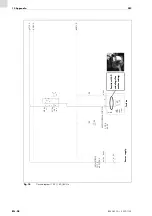
Страница 26: ...altplan 230 V 50 Hz 2 1 N W1 H07RN F M1 230V 1 1KW M 1 PE Q1M 3 3 1 3 5 F1M ETA 10A 6 2 4 PE 3 0 N 3 0 L1 3 0 3 4 2 1 3 3 PE L1 PE PE 450 750V 3G1 5 W2 ÖLFLEX CLASSIC 110 300 500V 3G0 75 GNYE MGH Netzanschluss Turbine BN BU GNYE X0 230V 50HZ Stecker Ferrit mit 2 Windungen Motorleistung ...

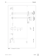
Страница 27: ...z 7 6 5 4 3 8 1 10 9 11 14 12 13 15 X3 X5 X4 X2 2 8 N 2 8 PE 2 PE 3 1 PE PE L N träge 1A F1 H Q B N A optional 24V GND Dig OUT 24V 24V 12V GND GND GND SIG SIG GND 0V DC 3 A1 A2 F1M 2 4 ÖLFLEX CLASSIC 130 H 300 500V 3x0 5 2 3 1 Out1 GND 12V X1 Hirschmann 4 polig l B1 FEC SGH A1 ESTA Interfacemodul 100 277VAC Anschluss Sensor intern Anschluss Sensor extern Stromsens or ...

Страница 28: ...lan 115 V 50 60 Hz M 1 M1 120V 1 1KW 60Hz 2 1 PE Q1M 3 3 1 3 5 F1M ETA 10A 6 2 4 PE 3 0 N 3 0 L1 3 0 3 4 2 1 3 3 PE PE W2 ÖLFLEX CLASSIC 110 500V 3G1 5 GNYE MGH Turbine N W1 H07RN F PE L1 450 750V 3G1 5 Netzanschluss BN BU GNYE Ferrit mit 2 Windungen Motorleistung ...

Страница 29: ...LEX CLASSIC 130 H 300 500V 3x0 5 GND 12V Hirschmann 4 polig B1 FEC SGH Out1 4 24V DC 14 13 2 2 4 3 5 Q1M Motorschütz 7 6 8 9 X3 Q Dig OUT GND 0V DC 3 A1 A2 F1M 2 4 2 8 L1 X1 2 Spannungsversorgung 5 4 3 1 X2 2 8 N 2 8 PE PE L N träge 1A F1 H 24V GND 4 2 4 6 2 4 A1 ESTA Interfacemodul 100 277VAC PE X1 2 1 3 1 Anschluss Sensor intern Anschluss Sensor extern Stromsens or ...

Страница 30: ...y instructions for the mains connection EN 6 2 7 Warning and notice signs EN 6 2 8 Emergency information EN 6 3 Product description EN 6 3 1 Technical data EN 7 3 2 Abbreviations EN 7 3 3 Nameplate EN 7 3 4 Signs and symbols used EN 8 4 Scope of delivery EN 8 4 1 Transport EN 8 4 2 Storage EN 8 5 Functional description EN 9 5 1 Control elements EN 10 6 Commissioning EN 10 6 1 Transport and install...

Страница 31: ...connection voltages of 115 V and 230 V These operating instructions only describe the FEC The FEC fume extraction system may be operated only with original ABICOR BINZEL spare parts 1 1 Marking This product fulfills the requirements that apply to the market to which it has been introduced A corresponding marking has been affixed to the product if required 1 2 EU Declaration of Conformity ...

Страница 32: ...ible dangers in Germany see TRBS 1203 Keep other people out of the work area Please observe the occupational health and safety regulations of the relevant country Ensure the work area is well lit and kept clean Occupational health and safety regulations of the relevant country for example in Germany Arbeitsschutzgesetz Occupational Health and Safety Act and Betriebssicherheitsverordnung Ordinance ...

Страница 33: ...lied With natural ventilation this is the case if the work area volume is at least 200 m e g surface of 58 m multiplied by room height of 3 5 m CAUTION Describes a potentially harmful situation If not avoided this may result in slight or minor injuries NOTICE Describes the risk of impairing work results or potential material damage to the equipment DANGER Danger of explosion due to use of welding ...

Страница 34: ...s must always be legible They may not be covered obscured painted over or removed 2 8 Emergency information In the event of an emergency immediately disconnect the following supplies Electrical power supply Compressed air supply Further measures can be found in the power source operating instructions or in the documentation for other peripheral devices 3 Product description NOTICE Make sure that t...

Страница 35: ...ound pressure level LpA1 1Measured according to the enveloping surface method according to DIN EN ISO 3744 measured at minimum volume flow uncertainty of measurement of noise approx 4 dB A 76 dB A Weight 25 kg Dimensions LxWxH 590 425 825 Tab 1 General information Ambient temperature 0 C to 40 C Relative humidity Up to 90 at 20 C Tab 2 Ambient conditions during operation Storage in a closed enviro...

Страница 36: ...7 Symbol Description Bullet symbol for instructions and lists Cross reference symbol refers to detailed supplementary or further information 1 Step s described in the text to be carried out in succession Fume extraction system with power supply of 115 230 V Extraction hose l 5 00 m Rubber connector Dust collecting bag 5 pieces FEC filter mat 2 pieces Tab 5 Scope of delivery Goods inspection Use th...

Страница 37: ... on the control panel 6 2 2 Automatic starting functions on page EN 13 DANGER Risk of fire Before installing and operating the fume extraction system please observe the following The extraction of welding fume during welding of oil wetted parts is not allowed It is not allowed to install or operate the system in areas subject to dust or gas explosion hazards Before commissioning it must be checked...

Страница 38: ...ir Status for operation is OK Filter Excellent Filter is clean Tab 7 Control elements 1 2 3 4 5 6 DANGER Risk of injury due to unexpected start The following instructions must be followed during all maintenance servicing assembly disassembly and repair work Switch off the FEC fume extraction system Close off the compressed air supply Disconnect all electrical connections NOTICE Note the following ...

Страница 39: ...ponents above persons or other devices Wear your personal protective equipment safety shoes with steel toe caps protective gloves ear protectors Send bystanders out of the danger zone Note the weight of the fume extraction system when lifting it 3 1 Technical data on page EN 7 CAUTION Risk of toppling Physical injury or damage to the fume extraction system due to improper assembly Disconnect the s...

Страница 40: ...tomatically starts the fume extraction process 1 Lay the ground cable 4 in the integrated automatic Start Stop system 6 2 Connect the ground cable 4 on one end to the power source and on the other end to the welding table for example 3 Press the A Auto button 2 on the control panel 1 5 1 Control elements on page EN 10 The FEC starts automatically when the welding process is started NOTICE An exter...

Страница 41: ...e assembly in the current clamp 3 Press the A Auto button 1 on the control panel The fume extraction system starts automatically when the welding process starts Button Description I Power Manual 0 Error OFF A Auto Integrated automatic Start Stop system active system runs only when welding occurs with a run on time of approx 20 seconds Tab 8 Automatic starting functions 1 A Auto button 2 Motor prot...

Страница 42: ...ram on page EN 26 1 Mounting screws 4 pieces 2 Air exhaust louver 3 Exhaust air hose Fig 8 Separate exhaust air hose 1 2 3 WARNING Electric shock Dangerous voltage due to defective cables Check all live cables and connections for proper installation and damage Replace any damaged deformed or worn parts NOTICE Before an electrical connection between the product and the power supply is established c...

Страница 43: ...ax 25 C CAUTION Risk of injury Damage from improper use Be sure that the housing does not make contact if you pass over edging because damage to the housing could occur Do not point the suction hose at a person and do not use the product to clean clothing Do not suction up flammable substances or liquids Provide sufficient ventilation during operation of the fume extraction system 6 1 Transport an...

Страница 44: ... supply Disconnect all electrical connections WARNING Electric shock Dangerous voltage due to defective cables Check all live cables and connections for proper installation and damage Replace any damaged deformed or worn parts NOTICE Before performing any maintenance and cleaning work suitable safety measures must be taken Maintenance and cleaning work on the fume extraction system may only be car...

Страница 45: ...e air outlets 9 4 Changing the filter on page EN 20 Visual inspection Dust in the turbine area Remove dust using an industrial vacuum cleaner or a damp disposable cloth Visual inspection Cable connections damaged Visual inspection Exhaust air filter untight or dirty 9 4 3 Replace the exhaust air filter on page EN 22 Check that the dust collecting drawer is air tight Filling level of the dust colle...

Страница 46: ...sing in the supplied dust collecting bag Fig 11 Emptying the filter housing on page EN 19 NOTICE Check and wear your personal protective equipment Personal protective equipment consists of protective clothing safety goggles a class P3 respiratory mask protective gloves and safety shoes Personal protective equipment must be worn when in the vicinity of the dust collecting bag as it is being filled ...

Страница 47: ...ng 2 and seal it 7 Dispose of the dust collecting bag in accordance with local regulations 8 Put the cap 1 back on NOTICE Check and wear your personal protective equipment Personal protective equipment consists of protective clothing safety goggles a class P3 respiratory mask protective gloves and safety shoes Personal protective equipment must be worn when in the vicinity of the dust collecting b...

Страница 48: ...housing 1 forward 4 Place the protective underlay 4 in the package with the new filter cartridge on the extraction system CAUTION Check and wear your personal protective equipment Personal protective equipment consists of protective clothing safety goggles a class P3 respiratory mask protective gloves and safety shoes Personal protective equipment must be worn when in the vicinity of the dust coll...

Страница 49: ...ilter housing 1 a few centimeters place the filter bag supplied with the new filter cartridge over the filter cartridge 3 5 Once the filter cartridge 3 is completely in the filter bag close the bag Dispose of it in accordance with local regulations 6 Insert the new filter cartridge 3 in the tipped filter housing 1 Mounting takes place in reverse order 1 Filter housing 2 Filter screws 3 Filter cart...

Страница 50: ...ver 1 7 Screw the mounting screws 2 in the cover 1 8 Switch on the fume extraction system NOTICE Check and wear your personal protective equipment Personal protective equipment consists of protective clothing safety goggles a class P3 respiratory mask protective gloves and safety shoes Personal protective equipment must be worn when in the vicinity of the dust collecting bag as it is being filled ...

Страница 51: ... onto its back 3 Loosen the four mounting screws 4 with the Allen key 4 Remove the cover grille 3 5 Remove the FEC filter pad 2 6 Insert the cleaned or new FEC filter pad 2 7 Mount the cover grille 3 8 Insert the four mounting screws 4 9 Tighten the four mounting screws 4 with the Allen key 10Bring the device into an upright position again 11 Remove the non slip base 1 Housing 2 FEC filter pad 3 C...

Страница 52: ...lass P3 respiratory mask protective gloves and safety shoes Fault Cause Troubleshooting Unit is not ready for operation Device component defective Have it checked and replaced Extraction system defective Have it checked and replaced Carbon brushes defective Have it checked and replaced Fume extraction system cannot be switched on Switch off the power to the system Check motor protective switch Red...

Страница 53: ...ust collecting bags is subject to special waste regulations The dust must not enter sewage systems or be disposed of together with normal household waste Observe the local and official regulations 12 3 Packaging ABICOR BINZEL has reduced the transport packaging to the necessary minimum The ability to recycle packaging materials is always considered during their selection DANGER Risk of injury due ...

Страница 54: ...diagram 230 V 50 Hz 2 1 N W1 H07RN F M1 230 V 1 1 KW M 1 PE Q1M 3 3 1 3 5 F1M ETA 10 A 6 2 4 PE 3 0 N 3 0 L1 3 0 3 4 2 1 3 3 PE L1 PE PE 450 750 V 3G1 5 W2 ÖLFLEX CLASSIC 110 300 500 V 3G0 75 GNYE MGH Power supply Turbine BN BU GNYE X0 230 V 50 Hz Plug Ferrite with 2 windings for motor rating ...

Страница 55: ... 1 10 9 11 14 12 13 15 X3 X5 X4 X2 2 8 N 2 8 PE 2 PE 3 1 PE PE L N slow blow 1 A F1 H Q B N A Optional 24 V GND Dig OUT 24 V 24 V 12 V GND GND GND SIG SIG GND 0 V DC 3 A1 A2 F1M 2 4 ÖLFLEX CLASSIC 130 H 300 500 V 3x0 5 2 3 1 Out1 GND 12 V X1 Hirschmann 4 pole l B1 FEC SGH A1 ESTA interface module 100 to 277 VAC Internal sensor connector External sensor connector Current sensor ...

Страница 56: ...115 V 50 60 Hz M 1 M1 120 V 1 1 KW 60 Hz 2 1 PE Q1M 3 3 1 3 5 F1M ETA 10 A 6 2 4 PE 3 0 N 3 0 L1 3 0 3 4 2 1 3 3 PE PE W2 ÖLFLEX CLASSIC 110 500 V 3G1 5 GNYE MGH Turbine N W1 H07RN F PE L1 450 750 V 3G1 5 Power supply BN BU GNYE Ferrite with 2 windings for motor rating ...

Страница 57: ...SSIC 130 H 300 500 V 3x0 5 GND 12 V Hirschmann 4 pole B1 FEC SGH Out1 4 24 V DC 14 13 2 2 4 3 5 Q1M Motor contactor 7 6 8 9 X3 Q Dig OUT GND 0 V DC 3 A1 A2 F1M 2 4 2 8 L1 X1 2 Power supply 5 4 3 1 X2 2 8 N 2 8 PE PE L N slow blow 1 A F1 H 24 V GND 4 2 4 6 2 4 A1 ESTA interface module 100 to 277 VAC PE X1 2 1 3 1 Internal sensor connector External sensor connector Current sensor ...

Страница 58: ...raccordement électrique FR 6 2 7 Plaques indicatrices et d avertissement FR 6 2 8 Instructions concernant les situations d urgence FR 6 3 Description du produit FR 6 3 1 Caractéristiques techniques FR 7 3 2 Abréviations FR 7 3 3 Plaque signalétique FR 7 3 4 Signes et symboles utilisés FR 8 4 Matériel fourni FR 8 4 1 Transport FR 8 4 2 Stockage FR 8 5 Description des fonctions FR 9 5 1 Éléments de ...

Страница 59: ...sponible pour une tension de réseau de 115 V et 230 V Ce mode d emploi décrit seulement le FEC Le dispositif d aspiration FEC ne doit être utilisé qu avec des pièces détachées ABICOR BINZEL d origine 1 1 Marquage Le produit répond aux exigences de mise sur le marché en vigueur des marchés respectifs Tous les marquages nécessaires sont apposés sur le produit 1 2 Déclaration de conformité UE ...

Страница 60: ...à l écart de la zone de travail Respectez les directives relatives à la sécurité du travail du pays concerné Veillez à ce que la zone de travail soit bien éclairée et propre Respectez les règles du pays concerné relatives à la sécurité et à la protection de la santé au travail Par exemple en Allemagne loi relative à la sécurité et à la protection de la santé au travail Arbeitsschutzgesetz et décre...

Страница 61: ...lle est donc suffisante si le volume d air dans la zone de travail s élève à au moins 200 m par ex une surface de 58 m avec une hauteur de 3 5 m ATTENTION Signale un risque éventuel qui s il n est pas évité peut entraîner des blessures plus ou moins graves AVIS Signale le risque d obtenir un résultat de travail non satisfaisant et de provoquer des dommages de l équipement DANGER Risque d explosion...

Страница 62: ...jours être lisibles Ils ne doivent pas être recouverts ou retirés 2 8 Instructions concernant les situations d urgence En cas d urgence coupez immédiatement les alimentations suivantes Alimentation électrique Alimentation en air comprimé D autres mesures à prendre sont décrites dans le mode d emploi de la source de courant ou dans la documentation des dispositifs périphériques supplémentaires 3 De...

Страница 63: ...e pression acoustique LpA moyen1 1mesuré sur une surface entourant la source de bruit selon DIN EN ISO 3744 avec un débit volumique minimum et une incertitude de mesure du bruit de 4 dB A 76 dB A Poids 25 kg Dimensions L x l x h 590 425 825 Tab 1 Informations générales Température de l air ambiant 0 C à 40 C Humidité relative de l air Jusqu à 90 à 20 C Tab 2 Conditions environnementales pendant l ...

Страница 64: ...e de renvoi faisant référence à des informations détaillées complémentaires ou supplémentaires 1 Étapes énumérées dans le texte et devant être exécutées dans l ordre Dispositif d aspiration avec raccordement au réseau 115 230 V Tuyau d aspiration l 5 00 m Pièce de raccordement en caoutchouc Sac à poussière 5 unités Mât filtrant FEC 2 unités Tab 5 Matériel fourni Contrôle à la réception Vérifiez qu...

Страница 65: ...e à la page FR 12 DANGER Risque d incendie Les points suivants doivent être respectés lors de l installation et l utilisation du dispositif d aspiration L aspiration de la fumée de soudage lors du soudage des pièces imprégnées d huile est interdite Il est interdit d installer ou d utiliser le dispositif dans des zones présentant un risque d explosion de poussières ou de gaz Avant la mise en servic...

Страница 66: ...permettant le fonctionnement Filter Excellent Filtre propre Tab 7 Éléments de commande 1 2 3 4 5 6 DANGER Risque de blessure en cas de démarrage inattendu Pendant toute la durée des travaux d entretien de maintenance d assemblage de démontage et de réparation respectez les points suivants Mettez le dispositif d aspiration FEC hors circuit Coupez l alimentation en air comprimé Débranchez tous les r...
Страница 67: ...sus de personnes ou d autres appareils Portez votre équipement de protection individuelle chaussures de sécurité avec embouts en acier gants de protection protections auditives Éloignez toute personne de la zone dangereuse extérieure Prenez en considération le poids du dispositif d aspiration lorsque vous le soulevez 3 1 Caractéristiques techniques à la page FR 7 ATTENTION Risque de basculement Ri...

Страница 68: ...rre automatiquement 1 Placez le câble de masse 4 sur le système automatique Marche Arrêt intégré 6 2 Raccordez le câble de masse 4 d un côté avec la source de courant et de l autre côté par exemple avec la table de soudage 3 Appuyez sur le bouton A Auto 2 du panneau de commande 1 5 1 Éléments de commande à la page FR 10 Lors de la mise en marche du processus de soudage le FEC est activé automatiqu...

Страница 69: ...z la sur le câble de masse ou le faisceau 3 Appuyez sur le bouton A Auto 1 du panneau de commande Dès que vous commencez le processus de soudage le processus d aspiration démarre aussi Bouton Description I Power Manuel 0 Error Arrêt A Auto Pince Marche Arrêt active l appareil ne fonctionne que si la soudure a lieu avec un temps d arrêt d environ 20 secondes Tab 8 Fonctions système de mise en march...

Страница 70: ... 4 pièces 2 Grille d aération 3 Tuyau de sortie d air Fig 8 Tuyau de sortie d air séparé 1 2 3 AVERTISSEMENT Risque de choc électrique Tension dangereuse en présence de câbles défectueux Veillez à ce que tous les câbles et raccordements sous tension soient correctement installés et ne soient pas endommagés Remplacez les pièces endommagées déformées ou usées AVIS Avant de raccorder le produit au se...

Страница 71: ...nipulation incorrecte Lors de passage sur un bord veillez à ce que le boîtier n entre pas en contact avec celui ci car cela pourrait endommager le boîtier Ne dirigez pas le tuyau d aspiration du dispositif d aspiration vers des personnes et ne l utilisez pas pour nettoyer des vêtements N aspirez pas de liquides ou de matières inflammables Lors de l utilisation du dispositif d aspiration assurez vo...

Страница 72: ...gereuse en présence de câbles défectueux Veillez à ce que tous les câbles et raccordements sous tension soient correctement installés et ne soient pas endommagés Remplacez les pièces endommagées déformées ou usées AVIS Prenez les mesures de précaution appropriées avant de procéder aux travaux d entretien et de nettoyage Le dispositif d aspiration ne doit être entretenu et nettoyé que dans les zone...

Страница 73: ...tures de sortie d air 9 4 Remplacement du filtre à la page FR 20 Contrôle visuel Retirez la poussière de la carcasse de turbine à l aide d un aspirateur industriel approprié ou d un chiffon humide jetable Contrôle visuel Câbles endommagés Contrôle visuel du filtre de sortie d air Filtre non étanche 9 4 3 Remplacement du filtre de sortie d air à la page FR 22 Contrôle de l étanchéité du bac Contrôl...

Страница 74: ...u boîtier de filtre à la page FR 19 AVIS Contrôlez et portez votre équipement de protection individuelle L équipement de protection individuelle comprend les vêtements de protection des lunettes de protection un masque de protection respiratoire de classe P3 des gants de protection et des chaussures de sécurité L accès est interdit aux personnes sans équipement de protection lors du transvasement ...

Страница 75: ... sac à poussière conformément aux dispositions locales 8 Replacez le couvercle de fermeture 1 AVIS Contrôlez et portez votre équipement de protection individuelle L équipement de protection individuelle comprend les vêtements de protection des lunettes de protection un masque de protection respiratoire de classe P3 des gants de protection et des chaussures de sécurité L accès est interdit aux pers...

Страница 76: ...ction 4 du paquet contenant la nouvelle cartouche filtrante sur le groupe d aspiration pour le protéger ATTENTION Contrôlez et portez votre équipement de protection individuelle L équipement de protection individuelle comprend les vêtements de protection des lunettes de protection un masque de protection respiratoire de classe P3 des gants de protection et des chaussures de sécurité L accès est in...

Страница 77: ...boîtier de filtre 1 mettez le sac à poussière fourni avec la cartouche filtrante sur la cartouche filtrante 3 5 Une fois que la cartouche filtrante 3 se trouve entièrement à l intérieur du sac à poussière fermez celui ci Procédez à une élimination conforme aux dispositions locales 6 Insérez la nouvelle cartouche filtrante 3 dans le boîtier de filtre basculé 1 Le montage s effectue dans l ordre inv...

Страница 78: ...cle 1 8 Mettez le dispositif d aspiration sous tension AVIS Contrôlez et portez votre équipement de protection individuelle L équipement de protection individuelle comprend les vêtements de protection des lunettes de protection un masque de protection respiratoire de classe P3 des gants de protection et des chaussures de sécurité L accès est interdit aux personnes sans équipement de protection lor...

Страница 79: ...xation 4 à l aide de la clé à six pans 4 Retirez la grille de protection 3 5 Retirez le mât filtrant 2 6 Insérez le mât filtrant 2 nettoyé ou neuf 7 Replacez la grille de protection 3 8 Insérez les quatre vis de fixation 4 9 Serrez les quatre vis de fixation 4 à l aide de la clé à six pans 10Remettez le dispositif à l endroit 11 Retirez la protection 1 Boîtier de filtre 2 Mat filtrant FEC 3 Grille...

Страница 80: ...ème Cause Solution Appareil non opérationnel Éléments du dispositif défectueux Contrôle et remplacement par du personnel qualifié Groupe d aspiration défectueux Contrôle et remplacement par du personnel qualifié Balais de charbon défectueux Contrôle et remplacement par du personnel qualifié Impossible de mettre sous tension le dispositif d aspiration Mettez l installation hors tension Vérification...

Страница 81: ...gales pour déchets spéciaux et la poussière ne doit pas parvenir dans les canalisations ou être éliminée avec les ordures ménagères Respectez les dispositions locales et administratives 12 3 Emballages ABICOR BINZEL a réduit l emballage de transport au minimum Lors du choix des matériaux d emballage nous veillons à ce que ces derniers soient recyclables DANGER Risque de blessure en cas de démarrag...

Страница 82: ...lectrique 230 V 50 Hz 2 1 N W1 H07RN F M1 230 V 1 1KW M 1 PE Q1M 3 3 1 3 5 F1M ETA 10 A 6 2 4 PE 3 0 N 3 0 L1 3 0 3 4 2 1 3 3 PE L1 PE PE 450 750 V 3G1 5 W2 ÖLFLEX CLASSIC 110 300 500 V 3G0 75 GNYE MGH Raccordement au réseau Turbine BN BU GNYE X0 230 V 50 Hz Fiche Ferrite avec 2 spires Puissance du moteur ...

Страница 83: ... 6 5 4 3 8 1 10 9 11 14 12 13 15 X3 X5 X4 X2 2 8 N 2 8 PE 2 PE 3 1 PE PE L N Action 1 A F1 H Q B s o en option 24 V GND Dig OUT 24 V 24 V 12 V GND GND GND SIG SIG GND 0 V c c 3 A1 A2 F1M 2 4 ÖLFLEX CLASSIC 130 H 300 500 V 3x0 5 2 3 1 Out1 GND 12 V X1 Hirschmann à 4 pôles l B1 FEC SGH A1 Module interface ESTA 100 277 V c a Raccord capteur interne Raccord capteur externe Détecteur de courant retardé...

Страница 84: ...que 115 V 50 60 Hz M 1 M1 120 V 1 1 KW 60 Hz 2 1 PE Q1M 3 3 1 3 5 F1M ETA 10 A 6 2 4 PE 3 N 3 L1 3 3 4 2 1 3 3 PE PE W2 ÖLFLEX CLASSIC 110 500 V 3G1 5 GNYE MGH Turbine N W1 H07RN F PE L1 450 750 V 3G1 5 Raccordement au réseau BN BU GNYE Ferrite avec 2 spires Puissance du moteur ...

Страница 85: ... H 300 500 V 3x0 5 GND 12 V Hirschmann à 4 pôles B1 FEC SGH Out1 4 24 V c c 14 13 2 2 4 3 5 Q1M Disjoncteur protecteur 7 6 8 9 X3 Q Dig OUT GND 0 V c c 3 A1 A2 F1M 2 4 2 8 L1 X1 2 Alimentation électrique 5 4 3 1 X2 2 8 N 2 8 PE PE L N Action 1 A F1 H 24 V GND 4 2 4 6 2 4 A1 Module interface ESTA 100 277 V c a PE X1 2 1 3 1 Raccord capteur interne Raccord capteur externe Détecteur de courant retard...

Страница 86: ...ión a la red ES 6 2 7 Señales indicadoras y de advertencia ES 6 2 8 Indicaciones para emergencias ES 6 3 Descripción del producto ES 6 3 1 Datos técnicos ES 7 3 2 Abreviaturas ES 7 3 3 Placa de identificación ES 7 3 4 Signos y símbolos utilizados ES 8 4 Relación de material suministrado ES 8 4 1 Transporte ES 8 4 2 Almacenamiento ES 8 5 Descripción del funcionamiento ES 9 5 1 Elementos de manejo E...

Страница 87: ...n 115 V y 230 V Este manual de instrucciones describe únicamente el FEC El extractor de humos FEC debe utilizarse exclusivamente con piezas de recambio originales de ABICOR BINZEL 1 1 Etiquetado El producto satisface los requisitos vigentes del mercado aplicable para su comercialización En caso necesario puede encontrar la identificación correspondiente en el producto 1 2 Declaración de conformida...

Страница 88: ... evaluar los trabajos que se le encargan y detectar posibles peligros en Alemania consulte la normativa TRBS 1203 El resto de las personas debe mantenerse alejado del área de trabajo Respete las normativas nacionales sobre seguridad en el trabajo El área de trabajo debe mantenerse bien iluminada y limpia Normas de protección laboral del país respectivo Por ejemplo en Alemania Ley de Protección Lab...

Страница 89: ...ventilación natural será suficiente cuando el volumen del área o espacio de trabajo sea como mínimo de 200 m p ej una superficie de 58 m por una altura de 3 5 m ATENCIÓN Indica una situación posiblemente dañina Si no se evita las consecuencias pueden ser lesiones leves o de poca importancia AVISO Significa la posibilidad de mermar los resultados de trabajo o de causar daños materiales en el equipa...

Страница 90: ...nes deben estar siempre visibles No se deben tapar con otros adhesivos ni recubrir pintar o eliminar 2 8 Indicaciones para emergencias En caso de emergencia interrumpa inmediatamente los siguientes suministros Alimentación de energía eléctrica Suministro de aire comprimido Para conocer más medidas consulte el manual de instrucciones de la fuente de corriente o la documentación del resto de aparato...

Страница 91: ... presión sonora LpA promedio1 1Medido según el método de control en una superficie de medición envolvente de acuerdo con DIN EN ISO 3744 con caudal mínimo incertidumbre de medición del ruido aprox 4 dB A 76 dB A Peso 25 kg Dimensiones largo x ancho x alto 590 425 825 Tab 1 Datos generales Temperatura ambiental De 0 C a 40 C Humedad relativa del aire Hasta 90 a 20 C Tab 2 Condiciones ambientales du...

Страница 92: ... la página ES 7 Símbolo Descripción Símbolo de enumeración para indicaciones de manejo y enumeraciones Símbolo de remisión a información detallada complementaria o adicional 1 Pasos de acción que deben realizarse en ese orden Extractor de humos con conexión a la red de 115 230 V Tubo flexible de aspiración l 5 00 m Conector de goma Bolsa para polvo 5 unidades Estera de filtro FEC 2 unidades Tab 5 ...

Страница 93: ...ido automático en la página ES 12 PELIGRO Riesgo de incendio Durante el montaje y la operación del extractor de humos se debe observar lo siguiente No está permitido extraer humos de soldadura en el caso de soldar componentes cubiertos de aceite El montaje y o la operación en atmósferas explosivas de polvo así como de gas no está permitidos Antes de la puesta en servicio se debe controlar si la te...

Страница 94: ...cto para operación Filter Excellent Filtro limpio Tab 7 Elementos de manejo 1 2 3 4 5 6 PELIGRO Riesgo de lesiones por arranque inesperado Lleve a cabo las acciones siguientes durante todos los trabajos de mantenimiento mantenimiento correctivo montaje desmontaje y reparación Desconecte el extractor de humos FEC Cierre el suministro de aire comprimido Interrumpa todas las conexiones eléctricas AVI...

Страница 95: ... de personas u otros aparatos Lleve puesto su equipo de protección individual zapatos de protección con puntera de acero guantes de protección y protección para los oídos Expulse de la zona de peligro a personas ajenas Tenga en cuenta el peso del extractor de humos antes de levantarlo 3 1 Datos técnicos en la página ES 7 ATENCIÓN Riesgo de vuelco Lesiones físicas o desperfectos del extractor de hu...

Страница 96: ...ión 1 Coloque el cable de tierra 4 en el sistema automáticio de arranque y parada integrado 6 2 Conecte el cable de tierra 4 por un lado a la fuente de corriente y por el otro lado p ej a la mesa de soldadura 3 Presione el botón A Auto 2 en el cuadro de manejo 5 1 Elementos de manejo en la página ES 10 Cuando comienza el proceso de soldadura el FEC arranca automáticamente AVISO Es posible instalar...

Страница 97: ...edor del cable de tierra o del ensamble de cables 3 Presione el botón A Auto 1 en el cuadro de manejo En cuanto comience con el proceso de soldadura se inicia también el proceso de aspiración Botón Descripción I Power Manual 0 Error Apagado A Auto Pinza de arranque y parada el aparato solo funciona durante la soldadura con un tiempo de inercia de aprox 20 segundos Tab 8 Funciones del encendido aut...

Страница 98: ...Tornillos de montaje 4 uds 2 Rejilla de extracción 3 Manguera de extracción Fig 8 Manguera de extracción independiente 1 2 3 ADVERTENCIA Electrocución Cables defectuosos pueden ocasionar peligro de alto voltaje Compruebe que todos los cables y las conexiones estén instalados correctamente y que no estén dañados Sustituya cualquier pieza dañada deformada o desgastada AVISO Antes de realizar la cone...

Страница 99: ...adecuada Procure que la carcasa no choque contra bordes pronunciados al desplazarla ya que podrían producirse desperfectos en la carcasa No dirija la manguera de aspiración del extractor de humos hacia ninguna persona y no la utilice para limpiar prendas de ropa No aspire ninguna sustancia ni líquido inflamables Proporcione una ventilación suficiente durante la operación del extractor de humos 6 1...

Страница 100: ...as ADVERTENCIA Electrocución Cables defectuosos pueden ocasionar peligro de alto voltaje Compruebe que todos los cables y las conexiones estén instalados correctamente y que no estén dañados Sustituya cualquier pieza dañada deformada o desgastada AVISO Antes de los trabajos de mantenimiento y limpieza se tienen que tomar las precauciones adecuadas El extractor de humos sólo puede someterse a un ma...

Страница 101: ...ión del filtro en la página ES 20 Examen visual Polvo en la turbina Si fuera necesario eliminar el polvo con una aspiradora industrial adecuada o con un trapo húmedo de un solo uso Examen visual Están dañadas las conexiones de cable Examen visual Tiene fugas el filtro de extracción 9 4 3 Sustitución del filtro de extracción en la página ES 22 Comprobación de hermeticidad del cajón Control del nive...

Страница 102: ...ra polvo suministrada 9 3 Vaciado de la carcasa del filtro en la página ES 19 AVISO Revise su equipo de protección individual antes de ponérselo El equipo de protección individual está compuesto por un traje de protección unas gafas de protección una máscara antigás de clase P3 guantes de protección y zapatos de protección Cuando se vierte el polvo separado en la bolsa para polvo no debe haber per...

Страница 103: ...a bolsa para polvo de acuerdo con las disposiciones locales 8 Monte de nuevo la tapa de cierre 1 AVISO Revise su equipo de protección individual antes de ponérselo El equipo de protección individual está compuesto por un traje de protección unas gafas de protección una máscara antigás de clase P3 guantes de protección y zapatos de protección Cuando se vierte el polvo separado en la bolsa para polv...

Страница 104: ...l filtro 1 4 Coloque la lámina de protección 4 del paquete del nuevo filtro de cartucho sobre el grupo de aspiración ATENCIÓN Revise su equipo de protección individual antes de ponérselo El equipo de protección individual está compuesto por un traje de protección unas gafas de protección una máscara antigás de clase P3 guantes de protección y zapatos de protección Cuando se vierte el polvo separad...

Страница 105: ...ltro 1 coloque la bolsa del filtro suministrada con el nuevo filtro de cartucho sobre el filtro de cartucho 3 5 Cuando el filtro de cartucho 3 esté completamente dentro de la bolsa del filtro cierre la bolsa Su eliminación debe seguir las estipulaciones locales 6 Introduzca el nuevo filtro de cartucho 3 en la carcasa del filtro 1 inclinada El montaje se lleva a cabo en orden inverso 1 Carcasa del ...

Страница 106: ...ornillos de montaje 2 de la tapa 1 8 Conecte el extractor de humos AVISO Revise su equipo de protección individual antes de ponérselo El equipo de protección individual está compuesto por un traje de protección unas gafas de protección una máscara antigás de clase P3 guantes de protección y zapatos de protección Cuando se vierte el polvo separado en la bolsa para polvo no debe haber personas sin e...

Страница 107: ...os de montaje 4 con la llave Allen 4 Retire la rejilla protectora 3 5 Extraiga la estera de filtro 2 6 Coloque la estera de filtro 2 limpia o una nueva 7 Coloque la rejilla protectora 3 8 Inserte los cuatro tornillos de montaje 4 9 Apriete los cuatro tornillos de montaje 4 con la llave Allen 10Vuelva a levantar el dispositivo 11 Retire la protección 1 Carcasa del filtro 2 Estera de filtro FEC 3 Re...

Страница 108: ... de protección Avería Causa Eliminación El equipo no funciona Componente del aparato defectuoso Comprobar y cambiar por personal técnico cualificado Grupo de aspiración defectuoso Comprobar y cambiar por personal técnico cualificado Escobillas de carbón defectuosas Comprobar y cambiar por personal técnico cualificado No es posible conectar el extractor de humos Desconectar la instalación de la red...

Страница 109: ... eliminación de residuos tóxicos El polvo no debe llegar al sistema de desagüe o eliminarse junto con la basura normal Observe las disposiciones locales y oficiales en vigor 12 3 Embalajes ABICOR BINZEL ha reducido el embalaje de transporte a lo estrictamente imprescindible Durante la selección de los materiales de embalaje se ha tenido en cuenta su posible reciclaje PELIGRO Riesgo de lesiones por...

Страница 110: ...eléctricas 230 V 50 Hz 2 1 N W1 H07RN F M1 230 V 1 1 KW M 1 PE Q1M 3 3 1 3 5 F1M ETA 10 A 6 2 4 PE 3 0 N 3 0 L1 3 0 3 4 2 1 3 3 PE L1 PE PE 450 750 V 3G1 5 W2 ÖLFLEX CLASSIC 110 300 500 V 3G0 75 GNYE MGH Conexión a la red Turbina BN BU GNYE X0 230 V 50 HZ Conector Ferrita con potencia del motor de 2 vueltas ...
Страница 111: ... 7 6 5 4 3 8 1 10 9 11 14 12 13 15 X3 X5 X4 X2 2 8 N 2 8 PE 2 PE 3 1 PE PE L N Lento 1 A F1 H Q B N D Opcional 24 V GND Dig OUT 24 V 24 V 12 V GND GND GND SIG SIG GND 0 V CC 3 A1 A2 F1M 2 4 ÖLFLEX CLASSIC 130 H 300 500 V 3x0 5 2 3 1 Out1 GND 12 V X1 Hirschmann 4 polos l B1 FEC SGH A1 Módulo de interfaz ESTA 100 277 V CA Conexión del sensor interno Conexión del sensor externo Sensor de corriente ...

Страница 112: ...as 115 V 50 60 Hz M 1 M1 120 V 1 1 KW 60 Hz 2 1 PE Q1M 3 3 1 3 5 F1M ETA 10 A 6 2 4 PE 3 0 N 3 0 L1 3 0 3 4 2 1 3 3 PE PE W2 ÖLFLEX CLASSIC 110 500 V 3G1 5 GNYE MGH Turbina N W1 H07RN F PE L1 450 750 V 3G1 5 Conexión a la red BN BU GNYE Ferrita con potencia del motor de 2 vueltas ...

Страница 113: ... 130 H 300 500 V 3x0 5 GND 12 V Hirschmann 4 polos B1 FEC SGH Out1 4 24 V CC 14 13 2 2 4 3 5 Q1M Protección del motor 7 6 8 9 X3 Q Dig OUT GND 0 V CC 3 A1 A2 F1M 2 4 2 8 L1 X1 2 Alimentación de tensión 5 4 3 1 X2 2 8 N 2 8 PE PE L N Lento 1 A F1 H 24 V GND 4 2 4 6 2 4 A1 Módulo de interfaz ESTA 100 277 V CA PE X1 2 1 3 1 Conexión del sensor interno Conexión del sensor externo Sensor de corriente ...

Страница 114: ...BAL 0533 0 2019 11 15 Notizen Notes Notes Notas FEC Notizen Notes Notes Notas ...

Страница 115: ...FEC Notizen Notes Notes Notas BAL 0533 0 2019 11 15 Notizen Notes Notes Notas ...

Страница 116: ...T E C H N O L O G Y F O R T H E W E L D E R S W O R L D w w w b i n z e l a b i c o r c o m Alexander Binzel Schweisstechnik GmbH Co KG Kiesacker 35418 Buseck GERMANY T 49 64 08 59 0 F 49 64 08 59 191 info binzel abicor com ...

Отзывы: