S1 Service manual
9
1.Radio Principle
:
1. Frequency configuration
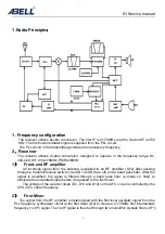
The receiver utilizes double conversion. The first IF is 21.70MHz and the Second IF is 450
KHz. The first local oscillator signal is supplied from the PLL circuit.
The PLL circuit in the transmitter generates the necessary frequency.
2
.
Receiver
The receiver utilizes double conversion, designed to operate in the frequency range DL:
400-420, DH: 450-470MHz, PMR446MHz
1
)
Front-end RF amplifier
An incoming signal from the antenna is applied to an RF amplifier (Q12) after passing
through a transmit/receive switch circuit (D7 and D8 are off) and a band pass filter. After the
signal is amplified, the signal is filtered through a band pass filter (a triode LC filter) to
eliminate the unwanted signal before it is passed to the first mixer.
The voltage of the varactor diode (D3, D13 and D14) on the AFC circuit is controlled by the
CPU (IC5) center frequency.
2
)
First
Mixer
The signal from the RF amplifier is heterodyned with the first local oscillator signal from the
PLL frequency synthesizer circuit at the first mixer (Q2) to create a 21.70MHz first intermediate
frequency (1st IF) signal. The 1st IF signal is then fed through two monolithic crystals filters (XF1)
Содержание S1
Страница 34: ...S1 Service manual 34 A Side ...
Страница 35: ...S1 Service manual 35 B Side ...
Страница 36: ...S1 Service manual 36 Explored view ...


