


VSN700 Data Logger Product Manual
- 19 -
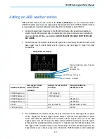
for the minimum required voltage and maximum allowed wire gauge. If unable to meet these
specs because of voltage drop then a separate power supply closer to the weather station
must be used. DO NOT USE CAT5/6 CABLE FOR THE POWER WIRES.
4.
Connect the other end of the shielded twisted-pair wire to the +9-24VDC and GND terminals
(terminals 6 and 5) on the data logger. It may be necessary to use a wire nut to attach the
multiple wires to the GND terminal on the data logger.
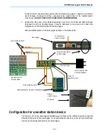
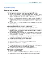
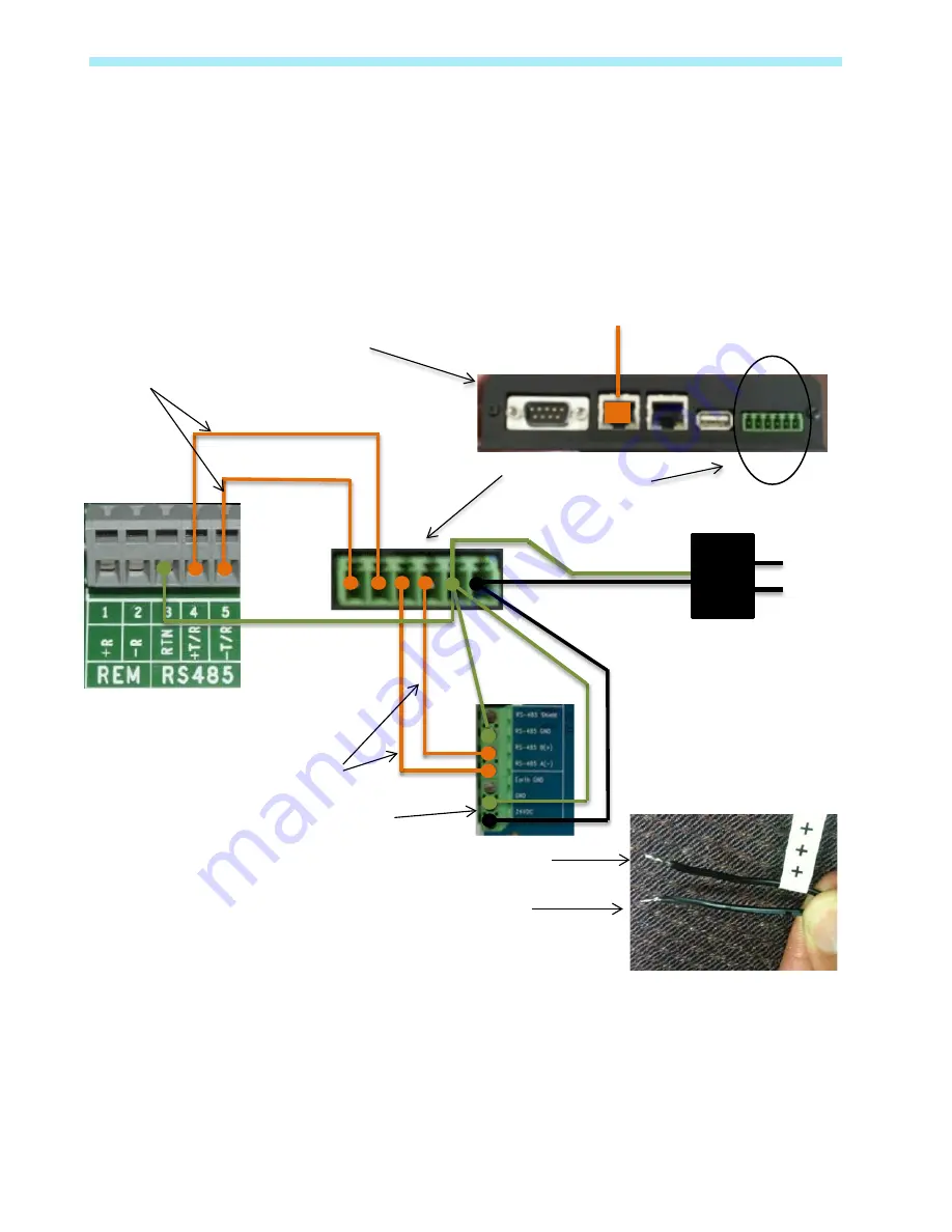
Wire the weather station to the data logger as shown in the figure below.
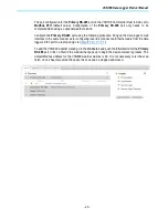
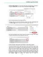
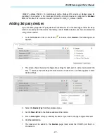
Configuration for a weather station device
The Devices list on the data logger’s Home page will show all the different devices connected
through all the ports on the data logger. It is essential that the devices you set up here match how
devices are physically connected to your data logger.
To Network via
Switch or Router
Screw Terminal Block
on Data Logger
Example Inverter
Terminal Block
Positive (+)
Negative (-)
100-240VAC/12VDC
Converter/Adapter
Data Logger
+12VDC Power
Use Twisted Pair Wire
Example Weather Station Terminal Block
Use Twisted Pair Wire
Power for
Weather Station
Adapter
+12VDC Power
DC Ground