


5:9
ABB
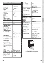
1
5
2
3
4
6
7
8
9
10
11
13
14
12
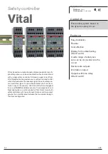
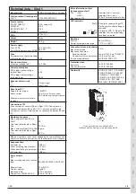
Technical data – Vital 1
Manufacturer
ABB AB/Jokab Safety, Sweden
Article number/Ordering data:
Vital 1
2TLA020052R0000
Level of safety
EN ISO 13849-1
EN 62061
IEC/EN 61508-1…7
EN 954-1
PL e, category 4
SIL 3
SIL 3
Category 4
PFH
D
2.74
×
10
-8
Colour
Grey
Weight
220 g
Power supply
Vital, A1-A2
From Vital to sensors/units, B1-B2
24 VDC ±15%
24 VDC
Fuse
An external fuse should be fitted
in the supply to A1
3 AT
Max line resistance
at nominal voltage to X1
150 Ohm
Power consumption
DC supply, nominal voltage
(without load)
DC supply, nominal voltage
(with max load)
3 W
48 W
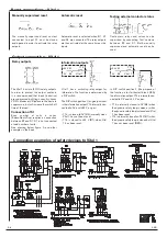
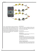
Dynamic safety circuit
T 1
R 1
Output signal
Input signal
Reset input X1
Supply for reset input
Reset current
Minimum contact closure time
for reset
+24VDC
30 mA max. (inrush current
300 mA during contact closure)
80 ms
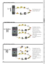
Connection of S1
Even numbers of sensors (Eden + Spot T/R + Tina) require a
connection between B1 and S1. S1 is not connected for odd
numbers of sensors. Odd number, no connection between B1 and
S1.
Number of sensors
Max. number of Eden/Tina to
Vital 1
Total max. cable length to Eden/
Tina
Max. number of Spot T/R to Vital
Total max. cable length to Spot
T/R
30
1000 m
6 pairs
600 m
Maximum number of units varies depending on the installation and
cable size. For more information, see the examples in this chapter.
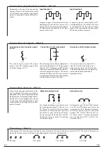
Response time
At Power on
When activating (input-output)
When deactivating (input-output)
At Power loss
< 65 ms
< 40 ms
< 48 ms
< 55 ms
Relay outputs
NO
Max switching capacity, resistive
load
Minimum load
Contact material
Mechanical life
External fuse (EN 60947-5-1)
2
6A/250 VAC/1500 VA/150W
10 mA/10V
AgCdO
>10
7
operations
6.3A or 4A slow
Relay information output
(changeover contact)
Y14
–(0V)
+(24V)
Max. load on Y14
Indicates Vital is not reset
Indicates Vital is reset
200 mA (Internal automatic fuse)
LED indication
On
T
R
1
2
Fixed light: supply voltage OK,
Flashing light: under-voltage or
overload.
T: Signal out OK. R: Signal in OK.
Indicates that the output relays
have been activated
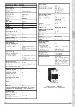
Mounting
DIN rail
Operating temperature range
35 mm DIN rail
-10°C to + 55°C
Connection blocks (detachable)
Max screw torque
Max connection area:
Solid conductors
Conductor with socket contact
Air and creep distance
1 Nm
1x4 mm
2
/2x1,5 mm
2
/12AWG
1x2,5 mm
2
/2x1 mm
2
4kV/2 DIN VDE 0110
Protection class
Enclosure
Connection blocks
IP 40 IEC 60529
IP 20 IEC 60529
Conformity
EN ISO 12100-1, -2, EN 954-1,
EN ISO 13849-1, EN 62061,
EN 60204-1, IEC 60664-1,
EN 61000-6-2, EN 61000-6-4
EN 60947-5-1, EN 1088,
EN 61496-1, IEC/EN 61508-1…7
Connector blocks are detachable
(without cables having to be disconnected)