Page 6
© 2023 ABB. All rights reserved.
BDFB Gateway_QSG
Rev. 2.0
QUICK START GUIDE
Step V6
-
Verify Connection to RS485 Daisy
-
Chain Network
1.
Connect a laptop or PC to
a. RS
-
232 port of the Gateway assembly (see Wiring Diagram).
or
b. The local port of the controller in the GPS system
2. If not already installed, download and install EasyView2
(see Reference Documents).
3. Start Easyview2.
4. Login as user
-
Password: lineage
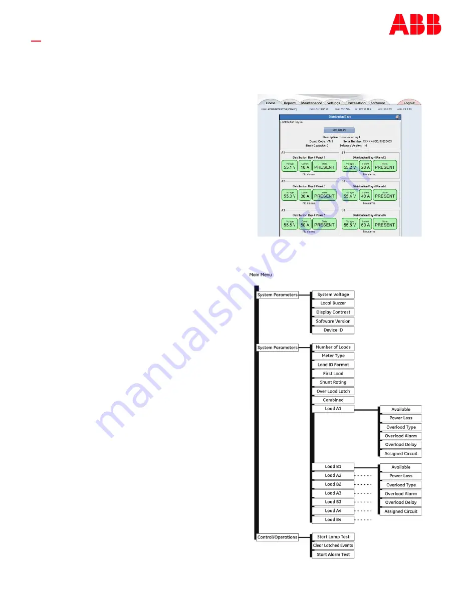
5. Confirm Gateway is connected to the VIM1EC by navigating
to Home
►
Distribution Bay Status to make sure you can see
the data for every BDFB load for each connected the VIM1EC.
Installation Completed.
Information: VIM1EC Meter
Each load bus is equipped with a shunt: 1500 A for
G7 and G8, 1600 A for G101 and G102. The VIM1C
monitors these shunts to determine actual currents
and the remaining capacity of each load bus.
VIM1C features include fuse/breaker alarms, power
loss alarms, individually configurable overload
thresholds, individually configurable power loss,
audible, and remote form
-
C output alarms. The VIM1
receives redundant power from the A and B panels
and external ABS.
Voltage and Current
-
VIM1C displays voltage, current,
and identifies each monitored load bus.
Alarm Indication
-
When an alarm occurs, the
backlight on the display changes color from green
(normal) to red (alarm active) and the front panel
text also changes from
“
No Alarms
”
to
“
Alarms.
”
Keys
–
Left and Right keys are used to navigate the
menu. Up and Down keys are used to adjust the
parameters.
Menus
-
Install VIM1EC Meter
-
V Steps
(continue)


