

10.
Connection of the communication and control signals
12.
Commissioning
11.
Instruments
UNO-2.0_3.0_3.6_4.2-TL-OUTD-Quick Installation Guide EN-RevA
EFFECTIVE 2015-07-22
© Copyright 2015 ABB. All Rights Reserved.
Specifications subject to change without notice.
8.
Line cable and protection devices
9.
Output connection (AC)
13.
Structure of the display menu
14.
Characteristics and T
echnical Data
Contact us
www.abb.com/solarinverters
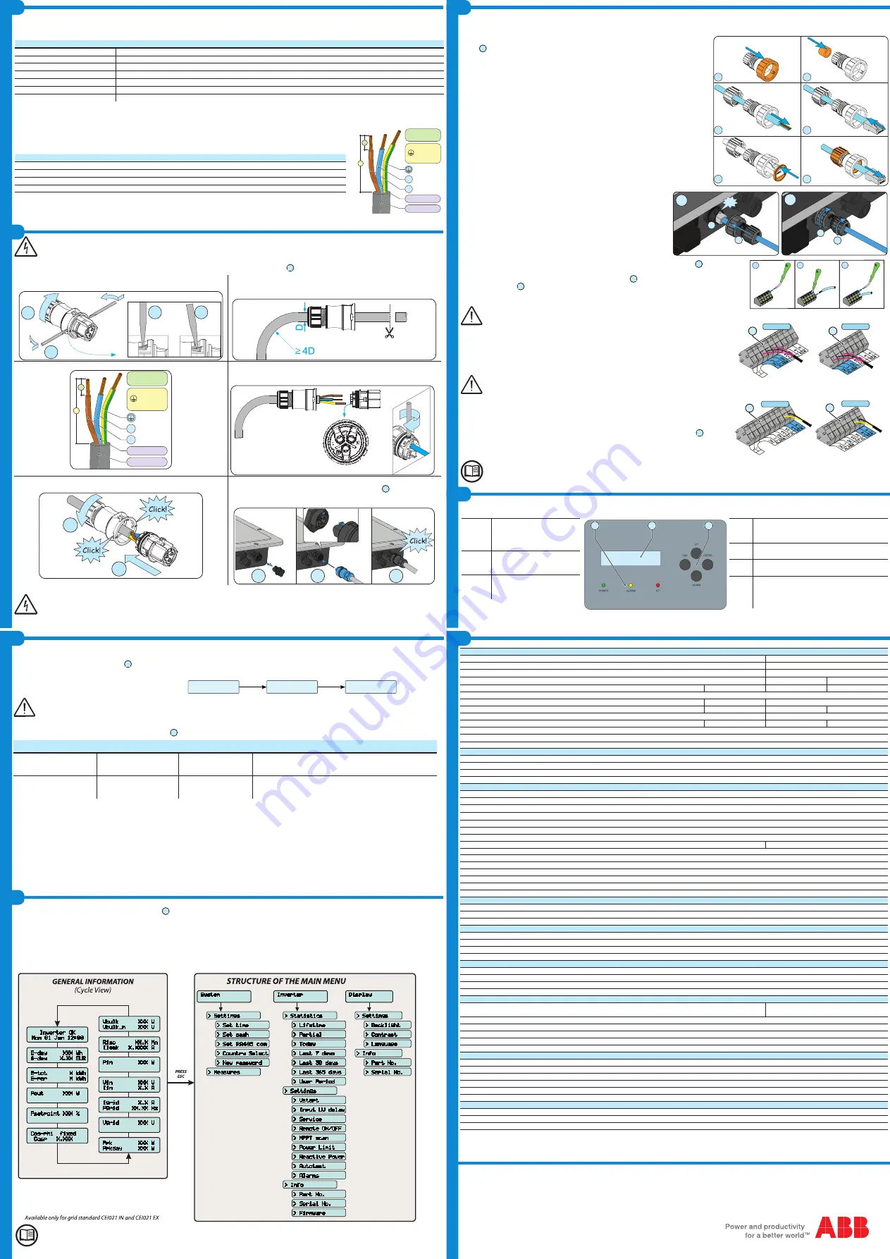
Connection of the communication signals (RS485 line)
On the inverter there is a RS485 communication line for connecting the inverter to monitoring devices. The line may also be used to store settings with the
dedicated advanced configuration software.
The connection of the serial communication cable must be made to the specific RS485 con
-
nector
14
present on the lower side of the inverter. An RJ45 connector must be installed on the
cable and the connector in its turn must be placed in the specific corresponding part (provided)
which allows the inverter to maintain its level of IP protection.
1. Install the blocking ring nut on the connector body
2. Install the gasket inside the connector body
3. Feed the cable through the holding ring nut and the connector body
4. Install the RJ45 connector on the cable and push it inside the connector body until it fits into
place.
5. Insert the gasket through the RJ45 connector and position it seated on the connector body
6. Extract the cable from the corresponding part just enough to enable connection with the
connector on the inverter.
At the end of the cable preparation stage, it is possible to proceed with connecting the commu-
nication line to the inverter.
1a. Install the cable on the RS485 connector on the inverter.
1b. Slide the corresponding part on to the cable until it is snug with the RS485
connector of the inverter. The insertion of the corresponding part is guided by
reference points which enable its correct positioning.
2a. Turn the fixing ring nut until the two connectors are blocked and check the
correctness of the installation.
2b. Turn the holding ring nut to a tightening torque of 0.6÷0.8Nm
Connection of the control signals
The connection of the control signals must be done on the specific signal terminal block
13
inside the
inverter using a flat screwdriver as shown in the figure:
Each cable which must be connected to a signal terminal block
13
must pass through one of the three
service cable glands
20
. Each cable gland (M20) can take a cable with diameter from 7 mm to 13 mm.
A gasket with two holes to insert into the cable gland which enables two separate cables of a maximum
diameter of 5 mm to be accommodated is available.
Warning! To ensure environmental protection rating IP65 it is necessary to tighten the cable gland with a torque of 2.5Nm
Use of the configurable relay
The inverter has a relay, the activation of which is configurable; it is possible to connect external
devices which, depending on the mode selected on the dedicated menu (Inverter > Settings > Alarms
> Set alarm type) can, for example, signal malfunctions. The operating modes that can be set are:
Production, Alarm, Alarm Configurable, Crepuscular, Alarm Configurable Latch, Alarm Configurable
ext, GoGo relay (Auto), GoGo relay (Slave).
The ALARM contact can only be used with systems which guarantee at least additional safety insulation (additional insulation in relation
to the input DC voltage)
Use of the remote ON/OFF signal
The connection and disconnection of the inverter to and from the grid can be controlled through an
external control. If the remote control function is operating, besides being dictated by the presence of
the normal parameters that allow the inverter to connect to the grid, start-up of the inverter also depen-
ds on the state of the terminal
R+
compared to the terminal
R-
present on the connector
13
. When the
R+ signal is brought to the same potential as the R- signal (that is to say when a short-circuit is created
between the two connector terminals) the inverter is disconnected from the grid.
For further information regarding the configuration and use of the communication and control signals terminal block, please see the
manual
The inverter commissioning procedure is as follows:
-Close the DC disconnect switch to supply the inverter with the photovoltaic generator voltage. If the inverter is equipped with a DC disconnect switch (-S
models), turn the DC disconnect switch
16
to the ON position.
-
When the inverter is connected to the power supply, the display will show a guided configuration procedure. Press ENTER to set the following:
Inverter date and time
Grid standard and corresponding display language
Warning! The settings become fixed after 24 hours of operation of the inverter (the inverter simply has to be powered by PV generator).
-After you have set the grid standard, the message "Initializing...Please Wait” is displayed. Regardless of the input voltage value, the inverter displays various
messages and changes the behaviour of the three LEDs
06
:
INPUT VOLTAGE
DISPLAYED MESSAGE
LED STATUS
DESCRIPTION
Vin < Vstart
Waiting sun
Green = FLASHING
Yellow = OFF
Red = OFF
The input voltage is not sufficient to enable connection to the grid.
Vin > Vstart
Vac Absent
Green = FLASHING
Yellow = ON
Red = OFF
The input voltage is sufficient to enable connection to the grid: the
inverter waits for the grid voltage to be present to make the parallel
connection.
The inverter is powered SOLELY by the voltage generated by the photovoltaic generator: the current in the attachment to the grid voltage is NOT
SUFFICIENT to switch on the inverter on its own.
-With the inverter in the "Missing Grid" status, close the AC switch downstream of the inverter thus applying the grid voltage to the inverter: the inverter checks
the grid voltage, measures the insulation resistance of the photovoltaic array with respect to ground and performs other auto-diagnostic tests. During the
preliminary checks on the parallel connection with the grid, the green LED keeps flashing, the others are off.
During the check on the grid voltage and the measurement of the insulation resistance, the voltage, grid frequency and insulation resistance values
measured by the inverter are displayed. The inverter ONLY creates a parallel connection with the grid if the grid and insulation resistance parameters
fall within the ranges foreseen by current regulations.
-If the outcome of the preliminary checks on the grid parallel is positive, the inverter connects to the grid and starts to export power to the grid. The green LED
remains constantly lit while the others are off.
LEDs and BUTTONS
, in various combinations, can be used to view the status or carry out complex actions that are described more fully in the manual.
LEDs
POWER
GREEN
Lit if the inverter is
working correctly. Flashes when
checking the grid or if there is
insufficient sunlight.
LEDs
ALARM
YELLOW
The inverter has
detected an anomaly. The ano-
maly is shown on the display.
LEDs
GFI
RED
Ground fault on the DC
side of the PV generator. The
error is shown on the display.
The ABB inverters are equipped with a graphic display
07
, consisting of 2 lines of 16 characters each, which can be used to:
-View the operating status of the inverter and the statistical data
-View service messages for the operator
-View alarm and fault messages
-Change the inverter settings
During the normal operation of the inverter the display cycles through the
GENERAL INFORMATION.
This information relates to the input and output parame-
ters and the inverter identification parameters. By pressing
ENTER
it is possible to block scrolling on a screen so that it is constantly displayed.
Press
ESC
to access the main menu which is structured as follows:
> Settings
> Measures
> Set time
> Set cash
> Set RA485 com
> Country Select
> New password
Inverter
> Statistics
> Settings
> Vstart
> Input UV delay
> Service
> Info
> Part No.
> Serial No.
> Firmware
> Remote ON/OFF
> MPPT scan
> Power Limit
> Reactive Power
> Autotest
> Alarms
> Lifetime
> Partial
> Today
> Last 7 days
> Last 30 days
> Last 365 days
> User Period
Display
> Settings
> Info
> Part No.
> Serial No.
> Backlight
> Contrast
> Language
*
Inverter OK
Mon 01 Jan 12:00
E-day XXX Wh
$-day X.XX EUR
E-tot X kWh
E-par X kWh
Pout XXX W
Psetpoint XXX %
Cos-phi fixed
Cosp X.XXX
Pin XXX W
Vin XXX V
Iin X.X A
Igrid X.X A
Fgrid XX.XX Hz
Vgrid XXX V
Ppk XXX W
Ppkday XXX W
Riso XX.X M©
Ileak X.XXXX A
Vbulk XXX V
Vbulk_m XXX V
System
*
Refer to the manual for details regarding use and functions available in the menu.
Warning! Before performing any of the operations described below, ensure the AC line downstream from the inverter has been correctly
disconnected.
For the connection of the inverter to the grid you need 3 connections: ground, neutral and phase. In any case, connection of the inverter to ground is mandatory.
The connection of the grid cable to the inverter is realized through the dedicated AC output connector.
10
by undertaking the following operations:
1. Remove the head of the connector by pressing on the two holding clips
and subsequently loosen the cable gland.
2
1
1a
1b
2. Feed the cable through the connector and cut the cable to correct length
Ensure that the cable's radius of curvature is more than 4 times the diameter
of the cable
3. Prepare the cable respecting the following measurements.
N
L
Max 6 mm²
x:
8 mm
Ø10÷14mm
x
y
y:
30mm
L,N 25 mm
4. Install the single wires (phase, neutral and ground) on the head of the
connector respecting the indications printed on each of the three connection
terminals (tightening torque 0.8...1Nm)
5. Close the connector and tighten the cable gland respecting the torque
(4+1Nm) in order to guarantee the IP65 protection level
1
2
6. Remove the pre-installed protective cover from the inverter.
Insert the corresponding part in the AC output connector
10
being careful
to align the reference points (present on both connectors) which prevent
connection errors.
2
1
3
In order to maintain the inverter's level of IP protection, the corresponding part must be obligatorily installed with the connected AC cable
or the protective cover, on the AC output connector.
In addition, the connector must not be subject to tensile forces (examples: do not connect weights to the AC cable, do not leave excess
cable windings hanging, etc).
UNO-2.0-TL-OUTD(-S) UNO-3.0-TL-OUTD(-S) UNO-3.6-TL-OUTD(-S) UNO-4.2-TL-OUTD(-S)
Input
Absolute maximum input voltage (V
max,abs
)
600 V
850 V
Input start-up voltage (V
start
)
100...300 V (default 150 V)
300...600 V (default 380 V)
Operating DC input voltage range (V
dcmin
...V
dcmax
)
0.7xV
start
...580 V (min 80V)
350...820 V
Rated DC input voltage (V
dcr
)
400 V
500 V
600 V
Input DC nominal power (P
dcr
)
2200 W
3200 W
3900 W
4500 W
Number of Independent MPPT
1
DC Voltage MPPT interval (V
MPPT min
... V
MPPT max
) a P
acr
180...500 V
200...500 V
380...700 V
Maximum DC input current (I
dc max
)
12.5 A
16.0 A
11.0 A
12.5 A
Maximum return current (AC side vs. DC side)
< 5 mA
4.7 A
Maximum short circuit current (I
sc max
)
15.0 A
20.0 A
15.0 A
15.0 A
Number of DC connection pairs in input
1
DC connection type
Quick fit PV connector
(1)
Type of photovoltaic panels that can be connected at input according to IEC 61730
Class A
Input protection
Reverse Polarity Protection
Yes, from current limited source
Input overvoltage protection - Varistors
Yes
Insulation check
Complying with the local standard
Characteristics of DC disconnect switch (version with DC disconnect switch)
600 V, 25A
1000 V, 16A
Output
AC grid connection type
Single phase
Nominal AC output power (P
acr@cosφ=1
)
2000 W
3000 W
3600 W
4200 W
Maximum AC output power (P
ac max@cosφ=1
)
2000 W
3000 W
3600 W
4200 W
Maximum apparent power (S
max
)
2000 VA
3000 VA
3600 VA
4200 VA
Nominal AC output voltage (V
acr
)
230 V
Output AC voltage range (V
acmin
...V
acmax
)
180...264 Vac
(2)
Maximum AC output current (I
ac max
)
10.0 A
15.0 A
16.0 A
20.0 A
Maximum fault current
18.3 A rms (20ms)
22.9 A rms (20ms)
Contribution to short-circuit current
12.0 A
17.0A
18.0A
22.0A
Inrush current
Negligible
Nominal output frequency (f
r
)
50 Hz / 60 Hz
Output frequency range (f
min
...f
max
)
47...53 / 57...63 Hz
(3)
Nominal power factor and adjustability interval
> 0.995, adj. ±0.8 with max Smax
Total current harmonic distortion
<3%
AC connections type
Female connector from panel
Output Protection
Anti-islanding protection
Complying with the local regulations
Maximum AC overcurrent protection
16.0 A
20.0 A
20.0 A
25.0 A
Output overvoltage protection - Varistor
2 (L - N / L - PE)
Operating Performance
Maximum efficiency (η
max
)
97.3%
98.4%
Weighted efficiency (EURO/CEC)
96% / -
97.5% / -
Power supply threshold
8.0 W
Night-time consumption
< 0.1W
Communication
Remote monitoring
VSN300 Wifi Logger Card (opt.), VSN700 Data Logger (opt.)
Wireless local monitoring
VSN300 Wifi Logger Card (opt.)
User interface
Display LCD with 16 characters x 2 lines
Wired Local Monitoring
PVI-USB-RS232_485 (opt.)
Environmental
Ambient temperature
-25...+60°C / -13...140°F with derating above
45°C / 113°F
-20...+60°C / -4...140°F with derating above
45°C / 113°F
Relative Humidity
0...100% condensing
Typical noise emission pressure
50 dB(A) @ 1 m
Maximum operating altitude without derating
2000 m / 6560 ft
External environment pollution rating
3
Environmental class
Outdoor
Physical
Degree of environmental protection
IP 65
Cooling system
Natural
Dimensions (H x W x D)
553mm x 418mm x 175mm / 21.8” x 16.5” x 6.9”
Weight
12 kg / 26.5 lb
Assembly system
Wall bracket
Overvoltage rating compliant with IEC 62109-1
II (DC input) III (AC output)
Safety
Insulation level
Without insulation transformer (TL)
Marking
CE (50Hz only)
Safety class
I
1. Refer to the document “String inverter – Product Manual appendix” available at www.abb.com/solarinverters to know the brand and the model of the quick fit connector
2. The output voltage range may vary according to the grid standard of the country of installation
3. The output frequency range may vary according to the grid standard of the country of installation
Note. Features not specifically mentioned in this data sheet are not included in the product
N
L
Max 6 mm²
x:
8 mm
Ø10÷14mm
x
y
y:
30mm
L,N 25 mm
08
07
06
ESC
It is used to access the main menu in order to go
back to the previous menu or to go back to the
previous digit to be edited.
UP
It is used to scroll up the menu options or to shift
the numerical scale in ascending order.
DOWN
It is used to scroll down the menu options or to
shift the numerical scale in descending order.
ENTER
It can be used to confirm an action, to access
the main menu or the submenu for the selected
option (indicated by the > symbol) or to switch to
the next digit to edit.
1
2
3
4
5
6
1
2
2a
2b
0.6÷0.8Nm
Click
1a
1b
1
2
2a
2b
0.6÷0.8Nm
Click
1a
1b
WIN
D
13
UNO-2.0/3.0
13
UNO-3.6/4.2
WIN
D
13
UNO-2.0/3.0
13
UNO-3.6/4.2
Config. Wizard
ENTER to START
Time hh:mm
Date DD MMM YYYY
GRID=Xxxxxxxx
Lang=Xxxxxxxx
ENTER
ENTER
Load protection breaker (AC disconnect switch) and line cable sizing
To protect the inverter AC connection line, it is recommended to install a device to protect against maximum current and leakage to ground, with the following
characteristics:
UNO-2.0-TL-OUTD
UNO-3.0-TL-OUTD
UNO-3.6-TL-OUTD
UNO-4.2-TL-OUTD
Type
Automatic circuit breaker with differential thermal-magnetic protection
Nominal voltage
230 V AC
Nominal current
16 A
20 A
20 A
25 A
Magnetic protection characteristic
B/C
Number of poles
2
Differential protection type
A/AC
Differential sensitivity
300 mA
ABB states that ABB high frequency transformerless inverters are not such in terms of their construction to input continuous ground fault current and therefore it
is not required that the differential installed downstream of the inverter is of type B in accordance with IEC 60755/A 2.
Characteristics and sizing of the line cable
The cable to be used must be tripolar. The cross-section of the AC line conductor must be sized in order to prevent unwanted
disconnections of the inverter from the grid due to high impedance of the line which connects the inverter to the power supply.
Line conductor cross section
Line conductor maximum length (m.)
PVI-2.0-TL-OUTD
PVI-3.0-TL-OUTD PVI-3.6-TL-OUTD PVI-4.2-TL-OUTD
1.5 mm²
10 m
6 m
5 m
4 m
2.5 mm²
15 m
11 m
10 m
8 m
4 mm²
25 m
19 m
16 m
13 m
6 mm²
38 m
29 m
24 m
20 m
The values are calculated in nominal power conditions, considering:
1. a power loss of not more than 1% along the line. 2. use of copper cable, with HEPR rubber insulation and positioned in
open air
a
b
c


