

1ZSE 5492-156 en, Rev. 4
|
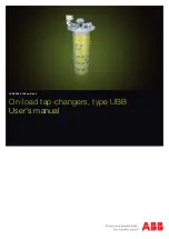
User's manual UBB
5
Operation
WARNING
The handcrank must not be inserted during electrical
operation.
WARNING
If the tap-changer is not in the exact position and the
handcrank is pulled out, the motor-drive mechanism
will start and go to the exact position if the power
supply is on.
WARNING
If a failure in power supply occurs during operation,
the operation will be completed when the power
returns.
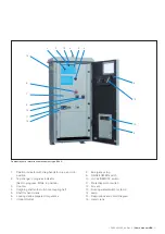
– The position indicator shows the actual tap-position.
– The draghands show the max. and min. tap-position
between which the tap-changer has been working since
last resetting.
–
For BUE:
The tap-change in progress indicator shows
POSITION in service position, RAISE when operating in
a raise operation and LOWER when operating in a lower
operation.
–
For BUL:
The tap-change in progress indicator shows
RED during operation and WHITE when the tap-changer is
in service position.
– For resetting of the emergency stop turn the knob
clockwise.
– The LOCAL/REMOTE switch. In position LOCAL the tap-
changer can be operated by the RAISE/LOWER switch. In
position LOCAL remote operation is rendered impossible.
In position REMOTE the tap-changer is operated from the
control room or by a voltage regulator. Local operation is
not possible in remote position.
– In case of a failure in power supply for the motor-drive
mechanism, it is possible to handcrank the tap-changer.
Put the handcrank on the shaft. Make sure it has entered
the slot in the shaft. Crank in the desired direction as per
the information plate above the shaft. The number of turns
for one step is also shown on the rating plate. When the
handcrank is inserted all electrical operations are rendered
impossible. Continue cranking until the tap-changer in
progress indicator shows POSITION for BUE or white
colour for BUL.
– Thermostat for extra heater (option). We recommend a
setting at +5 °C.
– Hygrostat for extra heater (option). We recommend a
setting at approximately 60 %.
– Outlet (option) with earth fault protector.
Normally the tap-changer is controlled by a voltage regulator
and no manual operation of the tap-changer and the motor-
drive mechanism is needed.
Maintenance schedule
CAUTION
To maintain the high reliability of the tap-changer it is
important that the inspections and the overhauls be
carried out at the interval stated on the rating plate.
CAUTION
If the frequency of operations is very low and the tap-
changer is filled with degassed oil after commissioning
or overhaul, the gas cushion should be restored one
month after filling. The absence of a gas cushion
means a risk for a false trip of the pressure relay. See
Restoring the gas cushion.
Maintenance of the tap-changer consists of three major steps:
– Inspection to be carried out by site personnel once a year
(see below)
– Overhaul to be carried out by a specialist at intervals stated
on the rating plate
– Contact replacement to be carried out by a specialist. The
possible need for replacement is decided during overhaul.
A specialist is a service engineer from ABB or an authorized
person trained by ABB for maintenance work on UB tap-
changers.