background image


Appendix


CI/TZIDC/110/120-EN 

TZIDC, TZIDC-110, TZIDC-120 

69 


8 Appendix 


8.1 

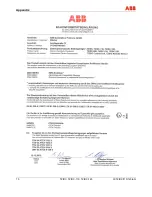
Approvals and certifications 


CE mark 


The version of the meter in your possession meets the requirements of the 
following European directives: 


-  EMC directive 2004/108/EC 


-  ATEX directive 94/9/EC 
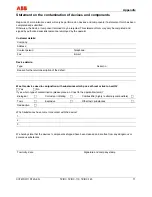
Explosion 
Protection 


Identification for intended use in potentially explosive atmospheres according 
to: 


-  ATEX directive (marking in addition to CE marking) 


- IEC 

standards 


-  FM Approvals (US) 


-  CSA International (Canada) 


IMPORTANT (NOTE) 

All documentation, declarations of conformity and certificates are available in ABB's download 
area. 
www.abb.com/instrumentation 


Содержание TZIDC

Страница 1: ...Commissioning Instruction CI TZIDC 110 120 EN Electro Pneumatic Positioner TZIDC TZIDC 110 TZIDC 120 For 4 20 mA two wire technology HART PROFIBUS PA FOUNDATION fieldbus...

Страница 2: ...2 32425 Minden Germany Tel 49 551 905 534 Fax 49 551 905 555 Customer service center Phone 49 180 5 222 580 Fax 49 621 381 931 29031 automation service de abb com Copyright 2013 by ABB Automation Prod...

Страница 3: ...safety instructions 10 3 Mounting 11 3 1 Operating conditions at installation site 11 3 2 Mechanical mount 11 3 2 1 General information 11 3 2 2 Mounting on linear actuators 13 3 2 3 Mounting on rota...

Страница 4: ...7 2 5 IECEx n 52 7 2 6 CSA International 53 7 2 7 CSA Certification Record 54 7 2 8 FM Approvals 55 7 2 9 FM Control Document 56 7 3 TZIDC 120 59 7 3 1 ATEX Ex i 59 7 3 2 ATEX Ex n 60 7 3 3 IECEx 61 7...

Страница 5: ...uctions can optimum protection of both personnel and the environment as well as safe and fault free operation of the device be ensured Information and symbols directly on the product must be observed...

Страница 6: ...vere injury WARNING Bodily injury This symbol in conjunction with the signal word Warning indicates a possibly dangerous situation Failure to observe this safety information may result in death or sev...

Страница 7: ...are version 3 Serial number 4 NL number 5 Year 6 Supply pressure 7 Input 8 Output 9 Dead 10 Options 1 6 Transport safety information Check the devices for possible damage that may have occurred during...

Страница 8: ...ved otherwise the type of electrical protection may be adversely affected Safe isolation of electrical circuits which are dangerous if touched is only guaranteed if the connected devices satisfy the r...

Страница 9: ...n protection management system Environmental awareness is an important part of our company policy Our products and solutions are intended to have a minimal impact on the environment and on people duri...

Страница 10: ...me in the future these substances will no longer be used in new product development 2 Ex relevant safety instructions Depending on the type of explosion protection an Ex label is attached to the left...

Страница 11: ...y settings Never start Autoadjust before restoring factory settings 3 1 Operating conditions at installation site IMPORTANT NOTE Before installation check whether the TZIDC TZIDC 110 TZIDC 120 positio...

Страница 12: ...ensor range for part turn actuators 3 Restricted working range 4 Working range IMPORTANT NOTE During installation make sure that the actuator travel or rotation angle for position feedback is implemen...

Страница 13: ...llowing table Fig 4 Mounting kit for linear actuators Lever 4 with follower pin for stroke adjustment 10 35 mm 0 39 1 38 inch or 20 100 mm 0 79 3 94 inch Follower guide 13 with two screws 10 spring wa...

Страница 14: ...ng the arrow marks 4 check whether the lever moves within the operating range between the arrows Hand tighten the screw 7 on the lever Hold the prepared positioner with loose mount bracket 1 to the ac...

Страница 15: ...ke Fig 8 Hold the mount bracket 3 in the proper position on the columnar yoke 2 Insert the U bolts 1 from the inside of the columnar yoke 2 through the holes for the mount bracket Add the washers 4 an...

Страница 16: ...of the valve to the operating range for the position sensor Moving the link point inward increases the rotation angle of the sensor Moving the link point outward reduces the sensor s rotation angle Ad...

Страница 17: ...e with VDI VDE 3845 the following mounting kit is available Fig 10 Adapter 1 with spring 5 each four screws M6 4 spring washers 3 and shim 2 to attach the mounting bracket 6 on the positioner each fou...

Страница 18: ...me position and rotational direction of the actuator determine in which position the feedback shaft 1 for the positioner must be pre adjusted and in which position the adapter 2 must be placed to enab...

Страница 19: ...20 19 2 Attach mounting bracket on the positioner Fig 12 1 Mounting bracket 3 Attach positioner to the actuator Fig 13 IMPORTANT NOTE After mounting the unit check whether the operating range for the...

Страница 20: ...ective screw terminals and hand tighten the screws access from above To connect a plug in module insert the wire ends from above in the appropriate screw terminals and hand tighten the screws access f...

Страница 21: ...ic device B Options 1 Control unit 2 Proximity switches 3 Microswitches IMPORTANT NOTE Keep cable shields as short as possible and connect on both sides M00767 3 1 2 51 52 41 42 515253 41 42 43 max 24...

Страница 22: ...or digital feedback 1 or service switch of emergency shutdown module 3 Module for digital position feedback 1 or terminals of the shutdown module 4 Installation kit for digital position feedback eithe...

Страница 23: ...0494 1 2 Fig 17 1 Simulation 2 Write access There are two jumpers on the mainboard that can be used to activate or block simulation mode and write access Set the jumpers as shown below M00495 1 2 Fig...

Страница 24: ...the housing there are two tap holes in four thread combinations to accommodate the cable entry and pneumatic connection Cable thread 1 2 14NPT air pipe thread 1 4 18 NPT Cable thread M20 x 1 5 air pi...

Страница 25: ...tches The two housings can be or are connected to a shielded 3 wire cable The maximum cable length is 10 m Installation and commissioning procedures are described in chapters 3 Mounting 5 Pneumatic co...

Страница 26: ...output 8 Binary input 9 Setpoint input 10 Ground connection 11 Proximity switches Microswitches switch 1 12 Proximity switches Microswitches switch 2 IMPORTANT NOTE The sensor and the electronics have...

Страница 27: ...th open circuit detection 4 to 18 k The maximum length of the shielded 3 wire cable is 10 m Installation and commissioning procedures are described in chapters 3 Mounting 5 Pneumatic connection and 6...

Страница 28: ...cable for remote position sensor 6 Connecting cable for remote position sensor 7 Binary output 8 Binary input 9 Setpoint input 10 Ground connection 11 Remote position sensor IMPORTANT NOTE Connect the...

Страница 29: ...d positioner can damage components The recommended pipe dimension is 6 x 1 mm Dust splinters or any other particles must be blown off the pipe before connecting To connect the air pipes G1 4 or 1 4 18...

Страница 30: ...t 1 The pressure values in the springless chamber exceed the max permissible limit values The diaphragms in the I P module or the actuator may sustain damage leading to device failure as a result Effe...

Страница 31: ...the control button Press again and hold down until the countdown ends Release this starts Autoadjust For part turn actuators 1 Press and hold down until is displayed release the control button Press a...

Страница 32: ...e1 with adaptation the control parameter 1 1 Control mode1 without adaptation the control parameter 1 2 Manual adjustment 2 in the operating range Adjust with or 3 1 3 Manual adjustment 2 in the senso...

Страница 33: ...osition check the end positions rotation angle is displayed in degrees for high speed mode press and simultaneously Recommended range between 28 28 for linear actuators between 57 57 for rotary actuat...

Страница 34: ...mall actuators It is not necessary under normal circumstances 1 The zero position is determined automatically and saved during Autoadjust counter clockwise CTCLOCKW for linear actuators and clockwise...

Страница 35: ...I 2 D Ex ia IIIC T51 C resp 81 C Db Type Examination Test Certificate T V 04 ATEX 2702 X Type Intrinsically safe equipment Device class II 2G Standards Device class Standards EN 60079 0 2009 EN 60079...

Страница 36: ...test certificate number PTB 00 ATEX 2049 X Proximity switches manuf by Pepperl Fuchs Plug in module for digital position feedback terminal 51 52 or 41 42 Maximum values Ui 30 V Ii 320 mA Pi 500 mW Ci...

Страница 37: ...d with gases from group IIA and a temperature class of T1 for auxiliary power the TZIDC positioner may only be used outdoors or inside sufficiently ventilated buildings The gas supplied must be kept s...

Страница 38: ...evices may only be connected to circuits in zone 2 if they are suitable for operation in zone 2 potentially explosive atmospheres and for the conditions prevailing at the installation location manufac...

Страница 39: ...015X Issue No 5 Type Intrinsic safety i or n type of protection Standards IEC 60079 0 2011 IEC 60079 11 2011 IEC 60079 15 2010 Type and designation TZIDC Ex ia IIC or Ex ib IIC Temperature class Ambie...

Страница 40: ...Switch output terminal 83 84 Maximum values Ui 30 V li 320 mA Pi 500 mW Ci 4 2 nF Li negligibly small Local communication interface LKS Only for connection to a programmer outside the potentially exp...

Страница 41: ...spection authority For the digital feedback with proximity switches circuit external measures must be implemented to prevent the rated voltage from being exceeded by more than 40 in the event of trans...

Страница 42: ...nF Li 0 uH Terminals 81 82 V max 30 V I max 110 mA Ci 4 2 nF Li 0 uH Terminals 83 84 V max 30 V I max 90 mA Ci 4 2 nF Li 0 uH Terminals 31 32 V max 30 V I max 110 mA Ci 6 6 nF Li 0 uH Terminals 41 42...

Страница 43: ...ls 11 12 V max 30 V I max 104 mA Ci 6 6 nF Li 0 uH Terminals 81 82 V max 30 V I max 110 mA Ci 3 7 nF Li 0 uH Terminals 83 84 V max 30 V I max 96 mA Ci 3 7 nF Li 0 uH Terminals 31 32 V max 30 V I max 1...

Страница 44: ...nity NI I 2 ABCD T4 Ta 85 C S II III 2 FG T4 Ta 85 C Type 4XMax Enity Parameters Per Control Drawings a Case mounting 1 2 3 4 or 9 b Input communication port 1 or 2 c Output safe protection 1 2 4 or 5...

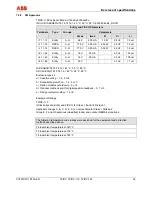
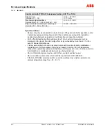
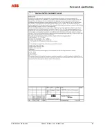
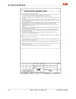
Страница 45: ...Ex relevant specifications CI TZIDC 110 120 EN TZIDC TZIDC 110 TZIDC 120 45 7 1 9 FM Control Document...

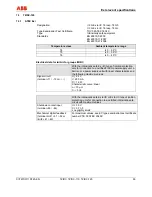
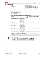
Страница 46: ...Ex relevant specifications 46 TZIDC TZIDC 110 TZIDC 120 CI TZIDC 110 120 EN...

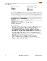
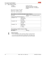
Страница 47: ...Ex relevant specifications CI TZIDC 110 120 EN TZIDC TZIDC 110 TZIDC 120 47...

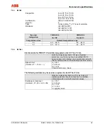
Страница 48: ...Ex relevant specifications 48 TZIDC TZIDC 110 TZIDC 120 CI TZIDC 110 120 EN...

Страница 49: ...e Ex i IIC type of ignition protection only for connection to a certified FISCO power supply unit a barrier or a power supply unit with linear characteristics and the following maximum values Signal c...

Страница 50: ...pheres and for the conditions prevailing at the installation location manufacturer s declaration or certificate from an inspection authority For the digital feedback with proximity switches circuit ex...

Страница 51: ...ctrical data for TZIDC 110 for ia ib ic designated as Ex i IIC T6 or T4 Gb With the intrinsically safe Ex i IIC type of ignition protection only for connection to a certified FISCO power supply unit a...

Страница 52: ...inspection authority For the digital feedback with proximity switches circuit external measures must be implemented to prevent the rated voltage from being exceeded by more than 40 in the event of tra...

Страница 53: ...ted 32 V DC max 15 mA powered by a SELV circuit Intrinsically safe with entity parameters of Terminals 11 12 V max 24 V I max 250 mA Ci 2 8 nF Li 7 2 uH Terminals 85 86 U max 30 V I max 50 mA Ci 3 8 n...

Страница 54: ...Input rated 32 V DC max 15 mA powered by a SELV Circuit Intrinsically safe with entity parameters of Terminals 11 12 V max 24 V I max 250 mA Ci 2 8 nF Li 7 2 uH Terminals 85 86 U max 30 V I max 50 mA...

Страница 55: ...1 uH NI I 2 ABCD T6 T5 T4 Ta 40 C 55 C 85 C S II III 2 EFG T6 T5 T4 Ta 40 C 55 C 85 C Enclosure type 4x a Case mounting 1 2 5 or 6 b Output safe protection 1 2 4 or 5 c Option modules shutdown 0 or 4...

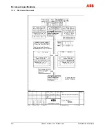
Страница 56: ...Ex relevant specifications 56 TZIDC TZIDC 110 TZIDC 120 CI TZIDC 110 120 EN 7 2 9 FM Control Document...

Страница 57: ...Ex relevant specifications CI TZIDC 110 120 EN TZIDC TZIDC 110 TZIDC 120 57...

Страница 58: ...Ex relevant specifications 58 TZIDC TZIDC 110 TZIDC 120 CI TZIDC 110 120 EN...

Страница 59: ...Ex i IIC type of ignition protection only for connection to a certified FISCO power supply unit a barrier or a power supply unit with linear characteristics and the following maximum values Signal ci...

Страница 60: ...mospheres and for the conditions prevailing at the installation location manufacturer s declaration or certificate from an inspection authority For the digital feedback with proximity switches circuit...

Страница 61: ...cal data for TZIDC 110 for ia ib ic designated as Ex i IIC T6 or T4 Gb With the intrinsically safe Ex i IIC type of ignition protection only for connection to a certified FISCO power supply unit a bar...

Страница 62: ...inspection authority For the digital feedback with proximity switches circuit external measures must be implemented to prevent the rated voltage from being exceeded by more than 40 in the event of tr...

Страница 63: ...ted 32 V DC max 15 mA powered by a SELV circuit Intrinsically safe with entity parameters of Terminals 11 12 V max 24 V I max 250 mA Ci 2 8 nF Li 7 2 uH Terminals 85 86 U max 30 V I max 50 mA Ci 3 8 n...

Страница 64: ...t rated 32 V DC max 15 mA powered by a SELV Circuit Intrinsically safe with entity parameters of Terminals 11 12 V max 24 V I max 250 mA Ci 2 8 nF Li 7 2 uH Terminals 85 86 U max 30 V I max 50 mA Ci 3...

Страница 65: ...I I 2 ABCD T6 T5 T4 Ta 40 C 55 C 85 C S II III 2 EFG T6 T5 T4 Ta 40 C 55 C 85 C Enclosure type 4x a Case mounting 1 2 5 or 6 b Output safe protection 1 2 4 or 5 c Option modules shutdown 0 or 4 d Opti...

Страница 66: ...Ex relevant specifications 66 TZIDC TZIDC 110 TZIDC 120 CI TZIDC 110 120 EN 7 3 9 FM Control Document...

Страница 67: ...Ex relevant specifications CI TZIDC 110 120 EN TZIDC TZIDC 110 TZIDC 120 67...

Страница 68: ...Ex relevant specifications 68 TZIDC TZIDC 110 TZIDC 120 CI TZIDC 110 120 EN...

Страница 69: ...ectives EMC directive 2004 108 EC ATEX directive 94 9 EC Explosion Protection Identification for intended use in potentially explosive atmospheres according to ATEX directive marking in addition to CE...

Страница 70: ...Appendix 70 TZIDC TZIDC 110 TZIDC 120 CI TZIDC 110 120 EN...

Страница 71: ...Contact person Telephone Fax E mail Device details Type Serial no Reason for the return description of the defect Was this device used in conjunction with substances which pose a threat or risk to hea...

Страница 72: ...oduct improvement and the right is reserved to modify the information contained herein without notice Printed in the Fed Rep of Germany 03 2013 ABB 2013 CI TZIDC 110 120 EN Rev C 3KXE341007R4401 Tel 0...

Отзывы: