background image

Safety 


8 TTR200 

OI/TTR200-EN 


Pos: 4.16 /Sicherheit/Allgemein/Organisatorische Maßnahmen/Pflichten des Betreibers @ 0\mod_1129728880599_3101.doc @ 3246 


1.6 

Operator liability  


Before the use of corrosive and abrasive measuring fluid, the operator must clarify the 
resistance of all parts that come into contact with the fluid to be measured. ABB will gladly 
support you with the selection, however, cannot accept any liability. 

The operators must strictly observe the applicable national regulations in their countries with 
regards to installation, function tests, repairs, and maintenance of electrical devices. 


Pos: 4.17 /Sicherheit/Allgemein/Organisatorische Maßnahmen/Qualifikation des Personals @ 0\mod_1129728800194_3101.doc @ 3247 


1.7 

Personnel qualification  


The installation, commissioning and maintenance of the device may only be carried out through 
trained specialist personell authorized by the plant operator. The specialist personnel must have 
read and understood the manual and comply with its instructions.  


Pos: 4.18 /Sicherheit/Allgemein/Organisatorische Maßnahmen/Rücksendung von Geräten @ 0\mod_1129730744499_3101.doc @ 3248 


1.8 Returning 

devices 


Use the original packaging or a suitably secure packaging for returning the device for repair or 
for recalibration. Include the properly filled out return form (see attachment) with the device. 

According to EC guidelines for hazardous materials, the owner of hazardous waste is 
responsible for its disposal or must observe the following regulations for its shipping: 

All delivered devices to ABB Automation Products GmbH must be free from any hazardous 
materials (acids, alkali, solvents, etc.).  


Pos: 4.19 /Sicherheit/Allgemein/Organisatorische Maßnahmen/Entsorgung @ 10\mod_1176447410937_3101.doc @ 81544 


1.9 Disposal 


ABB Automation Products GmbH actively promotes environmental consciousness and has an 
operational management system in accordance with DIN EN ISO 9001:2000, EN ISO 
14001:2004 and OHSAS 18001. Our products and solutions should have minimum impact on 
the environment and persons during manufacture, storage, transport, use and disposal. 

This includes the environmentally friendly use of natural resources. Through its publications 
ABB conducts an open dialog with the public. 

This product/solution is manufactured from materials that can be reused by specialized 
recycling companies. 

Содержание TTR200

Страница 1: ...Operating Instruction OI TTR200 EN Rail Mounted Temperature Transmitter TTR200 Pos 1 Titelblätter Copyright BA IA Temperatur TTR200 15 mod_1195562171781_3101 doc 141598 ...

Страница 2: ...any Tel 49 551 905 534 Fax 49 551 905 555 CCC support deapr de abb com Copyright 2008 by ABB Automation Products GmbH Subject to change without notice This document is protected by copyright It assists the user with the safe and efficient operation of the device The contents may not be copied or reproduced in whole or in excerpts without prior approval of the copyright holder Pos 3 Inhaltsverzeich...

Страница 3: ...fety information 10 1 13 Safety information on deinstallation 10 1 13 1 RoHS directive 2002 95 EC 10 2 Use in areas requiring ignition protection 11 2 1 Approvals 11 2 2 Level of protection 11 2 3 Electrostatic charging 11 2 4 Grounding 11 2 5 Interconnection 11 2 6 Configuration 11 2 7 Explosion protection relevant information 11 3 Design and function 12 4 Installation 12 5 Electrical connection ...

Страница 4: ...ters 27 7 7 1 Factory settings 29 8 TTR200 DTM diagnostic information 30 8 1 HART DTM diagnostic information 30 8 2 Analog output LED diagnostic information 30 9 Maintenance Repair 31 9 1 General information 31 9 2 Cleaning 31 10 Explosion protection relevant information 32 10 1 TTR200 E1 intrinsically safe 32 10 2 TTR200 E2 non incendive 32 11 Approvals 32 12 Technical data 33 12 1 Input 33 12 1 ...

Страница 5: ... It was tested and left the factory in a proper state The requirements in the manual as well as the documentation and certificates must be observed and followed in order to maintain this state for the period of operation The general safety requirements must be complied with completely during operation of the device In addition to the general information the individual chapters of the manual contai...

Страница 6: ...204 1 5 Labels and symbols Pos 4 10 Überschriften 1 1 1 1 spaltig Symbole und Signalwörter 20 mod_1208422698260_3101 doc 180868 1 5 1 Symbols and warnings Pos 4 11 Sicherheit Allgemein Symbole und Signalwörter 20 mod_1208422453167_3101 doc 180843 Danger Serious damage to health risk to life One of these symbols in conjunction with the Danger warning indicates an imminent danger If it is not avoide...

Страница 7: ...Refer to product documentation 5 Software revision number 6 Hardware revision number 7 Ambient temperature 8 TAG number 9 Sensor configuration 10 Technical data 11 Serial number 12 Order no 13 Order code 14 Manufacturer of transmitter 15 Country and year of manufacture 16 CE mark EC conformity 17 Model name 18 Terminal connection diagram Important The temperature range on the name plate 7 refers o...

Страница 8: ...n Rücksendung von Geräten 0 mod_1129730744499_3101 doc 3248 1 8 Returning devices Use the original packaging or a suitably secure packaging for returning the device for repair or for recalibration Include the properly filled out return form see attachment with the device According to EC guidelines for hazardous materials the owner of hazardous waste is responsible for its disposal or must observe ...

Страница 9: ...hrough air cushioned packaging Pos 4 22 Transport Allgemein Prüfung Material 16 mod_1196688849796_3101 doc 144028 Check the devices for possible damage that may have occurred from improper transport Damages in transit must be recorded on the transport documents All claims for damages must be submitted to the shipper without delay and before installation Pos 4 23 Leeres Modul mit einer Absatzmarke ...

Страница 10: ...s in the sections Safety information and Electrical connection and perform the specified steps in reverse order Pos 4 30 Sicherheit Temperatur TSP RoHS Richtlinie 2002 95 EG 9 mod_1178702920625_3101 doc 90274 1 13 1 RoHS directive 2002 95 EC With the Electrical and Electronic Equipment Act ElektroG in Germany the European directives 2002 96 EC WEEE and 2002 95 EC RoHs are translated to national la...

Страница 11: ...erature transmitter meet the IP 20 level of protection in accordance with IEC 60529 1989 2 3 Electrostatic charging When using the transmitter in zone 0 make sure you prevent electrostatic charging of the TTR200 E1H temperature transmitter observe warnings on equipment 2 4 Grounding If for functional reasons the intrinsically safe circuit has to be grounded by connection to the equipotential bondi...

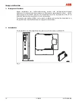
Страница 12: ...tters meet the requirements of the IP 20 protection class and are designed for 35 mm rail mounting The graphic user interface DTM can be used to configure poll and test the transmitter on a PC specific basis Handheld terminals also support communication Pos 10 Leeres Modul mit einer Absatzmarke IM 1 spaltig 14 mod_1194422545687_0 doc 136717 Pos 11 Überschriften 1 M O Montage 0 mod_1140519732218_31...

Страница 13: ...n the ignition proof version the guidelines according to the ignition proof norms are to be adhered to It must be checked whether the existing power supply corresponds with the specifications on the model plate and in the technical specifications in the Technical specifications section or the data sheet Important The signal cable wires must be provided with wire end sleeves The slotted screws of t...

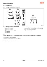
Страница 14: ...2 RTD resistance sensors e g Pt100 d RTD 2 wire circuit e RTD 3 wire circuit f RTD 4 wire circuit 3 Thermocouple Depending on the sensor model a variety of line materials can be used for sensor connections The integrated reference point makes it possible to directly connect thermal compensating lines 4 Voltage measurement Pos 14 8 Elektrischer Anschluss Temperatur TTR200 Anmerkung zu Anschlussplan...

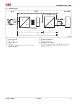
Страница 15: ... 3 5 kV DC 2 5 kV AC 60s A 1 2 3 4 6 7 8 D D A 12 30 Ex 42 V DC min 12 V DC 5 A 9 Fig 4 1 24 bit A D converter 2 Microcontroller 3 16 bit D A converter 4 HART signal 5 Load observe voltage drop refer to the section Terminal connection diagrams 6 Digital measuring accuracy 7 D A measuring accuracy 8 Overall measuring accuracy 9 Terminal 11 measurement of 4 20 mA output current without opening inter...

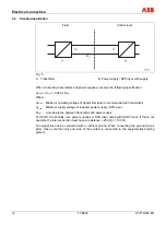
Страница 16: ...bserve the following specification UMmin USmin 0 02A x RLtg Where UMmin Minimum operating voltage of transmitter refer to technical data for transmitter USmin Minimum supply voltage of repeater power supply SPS input RLtg Line resistance between transmitter and power supply For HART functionality use power supplies or SPS input cards with HART mark If this is not possible the interconnection must ...

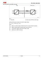
Страница 17: ... R250 increases the minimum supply voltage UMmin USmin 0 02A x RLtg R250 Where UMmin Minimum operating voltage of transmitter refer to technical data for transmitter USmin Minimum supply voltage of repeater power supply SPS input RLtg Line resistance between transmitter and power supply R250 Resistance for HART functionality Pos 14 15 Seitenumbruch 0 mod_1126532365768_3101 doc 3830 ...

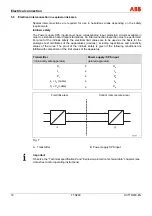
Страница 18: ...rd spark formation An interconnection inspection must be performed For proof of the intrinsic safety the electrical limit values are to be used as the basis for the prototype test certificates of the apparatuses devices including capacitance and inductivity values of the wires The proof of the intrinsic safety is given if the following conditions are fulfilled with comparison of the limit values o...

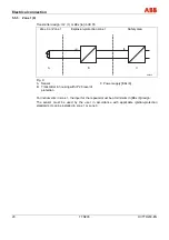
Страница 19: ...For additional information refer to the section Explosion protection relevant information or the data sheet 5 5 2 Zone 0 Transmitter design II 1G EEx ia IIC T6 Zone 0 Explosion protection zone 0 Safety area Fig 8 A Sensor B Transmitter in housing with IP 20 level of protection C Power supply EEx ia For instruments in zone 0 the input for the repeater must be in EEx ia design When using the transmi...

Страница 20: ... Safety area B C ib A00209 ia J A Fig 9 A Sensor B Transmitter in housing with IP 20 level of protection C Power supply EEx ib For instruments in zone 1 the input for the repeater must be at minimum in EEx ib design The sensor must be used by the user in accordance with applicable ignition protection standards It can be installed in zone 1 or zone 0 ...

Страница 21: ...fety area ib B C ib A00210 ia J A Fig 10 A Sensor B Transmitter in housing with IP 20 level of protection C Power supply EEx ib For instruments in zone 1 the input for the repeater must be at minimum in EEx ib design The sensor must be used by the user in accordance with applicable ignition protection standards It can be installed in zone 0 zone 1 or zone 20 ...

Страница 22: ... Transmitter in housing with IP 54 level of protection C Transmitter power supply For instruments in zone 2 the transmitter must be installed in its own housing with a minimum of IP 54 level of protection Ensure that in case of a disturbance the supply voltage cannot exceed 40 of the normal voltage Pos 15 Seitenumbruch 0 mod_1126532365768_3101 doc 3830 ...

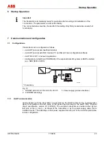
Страница 23: ...rationsarten TTR200 HART Kommunikation 15 mod_1195573382203_3101 doc 141935 Transmitters can be configured as follows via HART protocol and handheld terminal via HART protocol with FSK modem PC and Smart Vision configuration software via DTM in FDT 1 2 network applications Configuration via field bus PROFIBUS if the superordinate I O system is HART enabled e g ABB S800 or S900 A00212 HART 2 1 3 FS...

Страница 24: ...e bus can be connected via FSK modem as well as HART USB Profibus remote I O or HART Multiplexer Pos 19 8 Überschriften 1 1 1 1 spaltig Konfiguration mit der EDD 18 mod_1204121346262_3101 doc 165576 7 1 4 Configuration via EDD Pos 19 9 Konfiguration Parametrierung Temperatur TTR200 Konfiguration mit dem EDD 18 mod_1204121477731_3101 doc 165622 Configuration can also be performed with EDD master ap...

Страница 25: ...other hand be corrected only with a two point adjustment or two point calibration Pos 19 13 3 Überschriften 1 1 1 spaltig D F D A Analogausgangs Abgleich 4 und 20 mA Trim 8 mod_1174410063000_3101 doc 73783 7 4 D A analog output compensation 4 and 20 mA trim Pos 19 13 4 Konfiguration Parametrierung Temperatur TTR200 D A Analogausgangs Abgleich 4 und 20 mA Trim 15 mod_1195814050562_3101 doc 142437 O...

Страница 26: ...r TTR200 Kommunikation HART Tag Geräte Adressierung 15 mod_1195815541078_3101 doc 142514 For ease of identification each HART device features a configurable 8 digit HART tag Standard devices are come with the HART tag TI XXX When storing HART tags with more than 8 digits in the device use the Report parameter which supports up to 32 characters In addition to the HART tag each device has a HART add...

Страница 27: ...ermocouple type D ASTME988 Thermocouple type E IEC584 Thermocouple type J IEC584 Thermocouple type N IEC584 Thermocouple type R IEC584 Thermocouple type S IEC584 Thermocouple type T IEC584 Thermocouple type L DIN43710 Thermovoltage 125 125 mV Thermovoltage 125 1100mV Resistance 0 500 Ω Resistance 0 5000 Ω Pt10 IEC751 Pt50 IEC751 Pt200 IEC751 Pt500 IEC751 Pt10 JIS1604 Pt50 JIS1604 Pt200 JIS1604 Pt1...

Страница 28: ...r Range Value Depending on sensor type Damping Configurable condensation 63 output signal damping value Device Parametrize Voltage Output Damping 0 100 s Factory reset Configuration data is reset to factory settings for Pt100 3 wire 0 100 C damping off override adjustment data trim high low and DAC adjustment values are reset to factory settings Device Maintenance Reset to Factory Setting Yes OK D...

Страница 29: ...simul Sensor URL at 20 000 mA setpoint Device Maintenance Adjust DAC compensation fixed for amplification at 20 mA Analog current measurement value input min 19 5 max 20 5 mA Simulation Output signal simulation corresponding to the value specified Device Simulation 3 5 23 6 mA Pos 19 16 Leeres Modul mit einer Absatzmarke IM 1 spaltig 14 mod_1194422545687_0 doc 136717 Pos 19 17 Konfiguration Parame...

Страница 30: ... provides fault information about the sensor sensor lead and unit this information corresponds to Over underdrive for the output signal in the 4 20 mA current loop Important After connecting or switching on the supply voltage it may take up to 15 seconds before this is acknowledged by the green LED If neither green nor red LED lights up after this period the unit is defective As a rule the green o...

Страница 31: ...ed under normal operation no maintenance is required No on site repair or replacement of electronic parts is planned Warning Risk of explosion Faulty transmitters may not be placed into operation by the user Repairs must be performed in the production plant Pos 21 3 Wartung Reparatur Allgemein 1 1 Reinigung 0 mod_1132066200463_3101 doc 3550 9 2 Cleaning When cleaning the exterior of meters make su...

Страница 32: ...current Ii 130 mA Io 25 mA Io 50 mA Max power Pi 0 8 W Po 38 mW Po 60 mW Internal inductance Li 0 5 mH Li 0 mH Li 0 mH Internal capacitance Ci 5 nF Ci 49 nF Ci 49 nF Maximum permissible external inductance Lo 5 mH Lo 5 mH Maximum permissible external capacitance Co 1 55 µF Co 1 05 µF Pos 23 6 Wechsel ein auf zweispaltig 0 mod_1130421847171_3101 doc 3828 Change from one to two columns s 23 7 Wechse...

Страница 33: ...n detection in accordance with NAMUR NE 89 3 wire resistance reading 50 Ω 4 wire resistance reading 50 Ω 12 1 2 Thermocouples Voltages Types B E J K L N R S T U C D Voltages 125 125 mV 125 1100 mV Connecting cables Max sensor line resistance RW for each line 1 5 kΩ total 3 kΩ Sensor wire break monitoring in accordance with Namur NE 89 pulsed with 1 µA outside the measurement interval Thermocouple ...

Страница 34: ...der 0 100 s 1 depending on sensor type and sensor circuit Pos 28 13 Spaltenumbruch 0 mod_1132937966324_3101 doc 3831 Pos 28 14 Technische Daten Datenblatt Temperatur TTR Technische Daten Umgebungsbedingungen 15 mod_1194867265875_3101 doc 139817 kj 13 1 Ambient conditions Ambient temperature Standard 40 85 C 40 185 F For ignition proof design see prototype test certificate PTB 05 ATEX 2017 X Transp...

Страница 35: ...806 14 2 Permits and certifications Pos 35 1 Anhang Allgemein Zulassungen und Zertifizierungen CE _1 18 mod_1205231997500_3101 doc 169151 Zu Symbol Description CE mark By placing the CE mark on the name plate ABB Automation Products GmbH declares its conformance with the following directives EMC directive 89 336 EEC Ex approvals By placing the Ex mark on the name plate ABB Automation Products GmbH...

Страница 36: ...Appendix 36 TTR200 OI TTR200 EN Pos 38 Zertifikate Temperatur EG Konformatätserklärung_TTR200 300 18 mod_1204548362612_0 doc 166374 Pos 39 Seitenumbruch 0 mod_1126532365768_3101 doc 3830 ...

Страница 37: ...son Telephone Fax E Mail Device details Type Serial no Reason for the return description of the defect Was this device used for working with substances which pose a threat or health risk F Yes F No If yes which type of contamination please place an X next to the applicable items biological F corrosive irritating F combustible highly extremely combustible F toxic F explosive F other harmful substan...

Страница 38: ...cription of parameters 27 Design and function 12 Disposal 8 9 E Electrical connection 13 Electrical installation safety information 9 Electrical interconnection 18 Electrostatic charging 11 EMC directive 35 Explosion protection relevant information 32 F Factory settings 29 G General information 31 General Safety Information 5 Grounding 11 H HART variables 26 I Ignition protection approvals 35 Indu...

Страница 39: ... 6 T Technical data 33 Technical limits 6 Thermocouples 33 Transmission characteristics 33 Transport safety information 9 TTR200 DTM diagnostic information 30 Types 33 U Use in areas requiring ignition protection 11 V Voltages 33 W Warranty provision 6 WEEE directive 9 Write protection 24 Pos 42 4 Wechsel zwei auf einspaltig 0 mod_1130421955859_3101 doc 3829 Change from one to two columns Pos 43 R...

Страница 40: ...hout notice Printed in the Fed Rep of Germany 08 2008 ABB 2008 3KXT241001R4201 OI TTR200 EN Rev A ABB Limited Salterbeck Trading Estate Workington Cumbria CA14 5DS UK Tel 44 0 1946 830 611 Fax 44 0 1946 832 661 ABB Inc 125 E County Line Road Warminster PA 18974 USA Tel 1 215 674 6000 Fax 1 215 674 7183 ABB Automation Products GmbH Borsigstr 2 63755 Alzenau Germany Tel 49 551 905 534 Fax 49 551 905...

Отзывы: