background image

B0431

Emax X1-Tmax T7-Tmax T8

51/66

Doc N°

Mod.

Apparatus

Scale

Page No

1SDH000587R0002

3.8.3.3. 

Access to saved data from the system

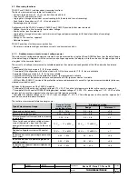
When the event associated with the stop event occurs or a stop command is received, the following data are saved in the record-

ing block:


- Data logger Trigger, which indicates the type of stop event (trigger) that has prompted the stoppage of the data logger;


- Time-stamp of the stop event (trigger) (day/hour + minutes/seconds/milliseconds)(4 words);


- Data logger max file, which indicates which is the max file with consistent data;


- Data logger max address, which indicates the max address number of a block with consistent data.

The following information is also stored:


- sample of currents L1, L2, L3, Ne


- V12, V23, V31 voltage samples


- digital inputs/outputs (among 16 possible options, e.g. inputs/outputs for Zone Selectivity, contact status, ...)


-  alarms1 (among 16 possible options, e.g.  L timing, G alarm, Prealarm)


- allarmi2 (tra 16 possibili. Es: UF timing, OV timing, Frequency error, RP timing)


- trips (among 16 possible options, e.g. tripping of L, S, I, G, UV, OF, ...).

The recordings are available in the protection release for as long as the unit is on (the data are lost in the absence of Vaux). 

Using Ekip Connect SW, the operator can perform a Download so that all the information in the recording can be stored in a single 

file (.abb format) and consulted with SD-DataViewer SW.

The next recording will be enabled following a Restart Trigger command.

3.8.3.4. 

Example of data logger operation

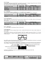
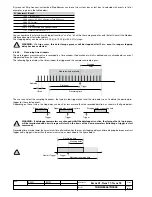
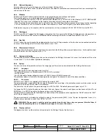
The following figure shows an example of how a trigger works, the data logger’s function, the effect of the stopping delay and of 

the restart and subsequent stop commands on the data saving procedure

Samples

available

Samples

available

Samples

Trigger

Waiting Trigger

Data logger triggered

Data logger stopped

Modbus commands

Stopping delay

Restart

Restart

Stop

Data logger enabled

3.8.4.  Zone selectivity
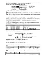
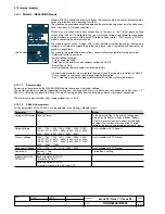
The LSI, LSIG and LSIRc versions of releases PR333/P and PR332/P possess inputs and outputs for the Zone selectivity function.

Name

Type

Description

K51/SZin (K51/DFin)

Digital input

Zone selectivity: input for protection S or “direct” “forward” input for protection 

K51/Gzin (K51/DBin)

Digital input

Zone selectivity: input for protection G or “reverse” “backward” direction input 

for protection D 

K51/SZout (K51/DFout)

Digital output

Zone selectivity: output for protection S or  “direct” “forward” output for protec-

tion D

K51/GZout (K51/DBout) Digital output

Zone selectivity: output for protection G or “reverse” “backward” output for 

protection D

The various different selectivity functions only operate if the protection release is powered by Vaux.

The digital output of each selectivity channel can be connected to up to 20 protection releases on the supply side in the selectiv-

ity chain.

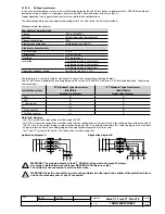
The maximum length of cable for zone selectivity, between two units, is 300 meters. Use corded shielded two-wire cable (per 

esempio cavo bifilare BELDEN 8762/8772). The shield must only be earthed on the circuit-breaker of the protection release on 

the supply side (ZSI side).

The operating mode is described in the chapters dedicated to each zone selectivity function: S (par. 1.6.3.3), G (1.6.8.2) and D 

(1.6.5.2).

B1751

Содержание Tmax T7

Страница 1: ...Emax X1 Tmax T7 Tmax T8 Operating istructions for T7 T8 X1 low voltage air circuit breakers protection releases Operating instructions 1SDH000587R0002 B1751...

Страница 2: ...afety principles and service operations are not included It is important to note that this documents contain warnings and cautions against certain specific service methods that could cause personal in...

Страница 3: ...functions 28 3 6 1 Notes about Protection Operation 28 3 6 2 Protection L 29 3 6 2 1 Thermal memory L 29 3 6 3 Protection S 29 3 6 3 1 Thermal memory S 29 3 6 3 2 Start up threshold S 30 3 6 3 3 Zone...

Страница 4: ...utotest 57 3 11 2 Trip test 57 3 11 3 Rc Test 57 3 11 4 Zone selectivity 57 3 11 5 COM module 58 3 11 6 Modulo SIGNALLING 58 3 11 7 MM Test 58 3 12 Putting into service and recommendations 59 3 12 1 I...

Страница 5: ...separate power supply unit S S S Ekip T P External unit for power supply communication and testing via USB T T T PR010 T External unit for tests T T T Key S standard function unit O optional function...

Страница 6: ...one selectivity SW Software TC Trip Coil opening solenoid Rc Current sensor for residual current reading Trip CB opening action generated by protection release TV Voltage transformer Un Rated voltage...

Страница 7: ...ccordance with the protection settings Dip switches on the front allow the main protections and settings to be adjusted while the state of the protection release is indi cated by the leds of the front...

Страница 8: ...Tmax T7 T8 series any size The CB model establishes the rated uninterrupted current the circuit breaker is able to support lu The adjustable protections L S I and G refer to the In size defined by th...

Страница 9: ...switches and leds of protection S are available with release versions LSI and LSIG The dip switches and leds of protection G are available with release version LSIG 2 3 1 Dip switches The dip switches...

Страница 10: ...he protection of Ne is ON in the 3P circuit breaker without Ne ext wiring error The cause of tripping CS Error Rating Plug Error is displayed in the presence of Vaux and or PR030 B connected during th...

Страница 11: ...time is calculated according to the value of If For fault currents If 12ln the tripping time of the protection is given by the expression t s If the calculated value is less than 1 second the real tri...

Страница 12: ...r given in In and s PR331 P is able to provide earth fault protection created inside the protection release by vectorally adding together the phase and neutral currents The fault current is defined by...

Страница 13: ...0 5 0 525 0 55 0 575 0 6 0 625 0 65 0 675 0 7 0 725 0 75 0 775 0 8 0 825 0 85 0 875 0 9 0 925 0 975 1 x In t1 3 12 24 36 48 72 108 144 s 1 If 3I1 Release between 1 05 and 1 2 x I1 10 If 6 x In 20 If...

Страница 14: ...ratus Scale Page No 1SDH000587R0002 2 4 9 Trip curves The trip curves provided are merely for guidance and only show a sub group of the possible selections 2 4 9 1 Trip curves for functions L I 2 4 9...

Страница 15: ...B0431 Emax X1 Tmax T7 Tmax T8 15 66 Doc No Model Apparatus Scale Page No 1SDH000587R0002 2 4 9 3 Trip curves for functions L S t k I t k 2 4 9 4 Trip curves for function G t k I2 t k B1751...

Страница 16: ...ontact S51 P1 PR331 P has an external contact which can be configured by the customer and is useful for monitoring a series of events including alarms and protection trips The configuration options of...

Страница 17: ...t there is an error in the CS and or TC connections 2 6 4 Connection of current sensor for external neutral WARNING Remember to set the InN in the appropriate way if the current sensor for the externa...

Страница 18: ...ip occurs FN 6 Expected trip does not happen Function OFF FN enable protection function 7 LEDs irregularly turned on see par 1 3 2 8 Unexpected trip see par 1 3 2 9 L LED orange flashing FN 2 8 2 In t...

Страница 19: ...n releases PR332 P for SACE Emax X1 and SACE Tmax T7 T8 circuit breakers and PR333 P for X1 circuit breakers are electronic devices with functions for monitoring and for protecting against fault curre...

Страница 20: ...tection against instantaneous short circuits at high currents known as Iinst 3 3 2 Functions PR332 P and PR333 P include various different functions depending on the version and configuration chosen R...

Страница 21: ...an be used to temporarily energize and communicate the protection release via PC Like PR010 T it also allows the protection release to be tested again via PC The HMI030 switchgear display expands the...

Страница 22: ...ak factor 2 1 2xIn in accordance with IEC 60947 annex F Consult ABB for a dedicated analysis if there are higher peak factors Primary voltage characteristics Range Three phase minimum phase to phase v...

Страница 23: ...tate Description ALARM Red OFF No protection or delay alarm ON Flashing 1Hz Delay in progress for one or more of the following protections current L S G voltage UV OV RV frequency OF UF active power r...

Страница 24: ...SW register corresponding to Trip is reset Press iTest when the protection release is off to obtain a description of the last event that led to the protection release being shut off function available...

Страница 25: ...on with an icon showing the type of alarm in question information active delay danger Icon Message Description Configuration Inconsistent parameters or inconsistent data between key plug and pro tecti...

Страница 26: ...ession cancelled Failed Programming session rejected 3 4 3 3 Operating icons An area with icons showing the operating conditions of the protection release is available on the display The area is at th...

Страница 27: ...SC from the default page includes 5 options Main Menu Option Description Paragraph 1 Protections Reading and adjustment of all the protections available 1 6 2 Measurements Reading of all the measureme...

Страница 28: ...Curve Trip enabling Zone selectivity Startup O 4 O 4 Protection Gext Idn Enabling Threshold Time O 5 O 6 Protection U Enabling Threshold Time Curve Trip enabling S S Protection UV Enabling Threshold...

Страница 29: ...does not set to the alarm status for current values of less than 1 05 xI1 the protection release will set to the alarm status for current values exceeding 1 2 xI1 3 6 2 1 Thermal memory L The thermal...

Страница 30: ...ts of the circuit breakers at the head of each chain must be empty Area 1 Release 1a Release 1b ZSO ZSO 1a 1b Release 1 ZSI1 ZSO1 Area 2 Area n Release 2 ZSI2 ZSO2 Release 0 ZSI0 Release n ZSIn ZSOn A...

Страница 31: ...h to low Top Bottom from low to high Bottom Top selectable in the menu Modules Measuring Module PR330 V As a result the currents in the circuit breaker will be defined as forward or backward if their...

Страница 32: ...lt If beyond the threshold I7 in one of the sections of the system Load A the final circuit breakers for the section in question Release1 and Release2 communicate the presence of the fault to the conn...

Страница 33: ...ss than t4 the real tripping time is forced to t4 t s t4 NOTES t s envisaged tripping time If fault current given in In example 0 4In I4 t4 protection G parameters set by the user given in In and s Th...

Страница 34: ...ivate the inputs and outputs e g output K51 GZout is activated if the fault current exceeds one of the two protection thresholds 3 6 10 Residual current protection Rc Protection Rc provides protection...

Страница 35: ...the preset time interval t9 and then opens As already described for protection U the function acts in the same way if an Alarm occurs opening depending on the state of the CB and the presence of curr...

Страница 36: ...erator to configure a second set of all the avail able protections called Set B The event for automatic set change over can also be associated in the settings menu If Dual Set is enabled the protectio...

Страница 37: ...requiring shorter reaction times than those provided by the instantaneous short circuit protection The protection cannot be disabled It has a single fixed time protection curve and the threshold leve...

Страница 38: ...10 or 40ms RP t k 0 3xPn P11 0 1xPn step 0 02 Pn 0 5 s t11 25 s step 0 1 s 5 The best of the two data 10 o 40 ms UF 0 9fn f12 0 99fn step 0 01 fn 0 5 s t12 3 s step 0 1 s 5 The best of the two data 1...

Страница 39: ...ven are for guidance and only show a sub group of the possible selections The graphs do not include the curves of protection functions with the the same principle S2 S MCR and MM I Gext G 3 6 24 1 Tri...

Страница 40: ...ctions L S t k I2 I t s 10 1 10 2 1 10 102 103 104 10 3 1 10 100 10 1 x In 0 4 1 1 5 15 1 5 15 0 6 10 0 6 10 0 05 0 8 0 4 1 3 144 L I S t k I 2 3 6 24 3 Trip curves for functions L S t k I t s 10 1 10...

Страница 41: ...ip curves for function L in accordance with IEC 60255 151 type A t s 10 1 1 10 102 103 104 10 1 1 10 100 x In 3 144 0 4 1 0 4 1 L k 0 14 0 02 3 6 24 5 Trip curves for function L in accordance with IEC...

Страница 42: ...c N Mod Apparatus Scale Page No 1SDH000587R0002 3 6 24 6 Trip curves for function L in accordance with IEC 60255 151 type C t s 10 1 1 10 102 103 104 1 10 100 10 1 x In 0 4 1 0 4 1 3 144 L k 80 2 3 6...

Страница 43: ...Page No 1SDH000587R0002 3 6 24 8 Trip curves for function D t s 1 10 100 1 10 102 103 104 10 2 x In 10 1 10 1 D 10 0 2 0 8 0 6 10 0 6 10 3 6 24 9 Trip curves for function U t s 1 10 10 1 1 10 102 103...

Страница 44: ...002 3 6 24 10 Trip curves for function UV t s 10 1 10 2 1 10 102 103 104 0 3 0 5 0 7 0 9 1 1 1 3 x Un 0 1 0 5 0 95 0 5 0 95 10 0 1 5 5 UV 3 6 24 11 Trip curves for function OV t s 10 1 10 2 1 10 102 1...

Страница 45: ...DH000587R0002 3 6 24 12 Trip curves for function RV t s 10 1 1 10 102 103 104 0 0 2 0 4 0 6 0 8 1 x Un 1 2 10 0 5 30 0 5 0 1 0 4 30 0 1 0 4 RV 3 6 24 13 Trip curves for function RP t s 10 1 1 10 102 1...

Страница 46: ...our pole CB phase currents I1 I2 I3 Ine are available LSIG and LSIG MM version of the protection release Ig measurement available LSIG and version of the protection release and presence of SGR Ige mea...

Страница 47: ...P and PR333 P are able to record up to 80 events Use the UP and DOWN buttons to scroll all the events 3 7 4 Measurements Log register PR332 P and PR333 P can record various different measurements and...

Страница 48: ...Range of values measured by the protection release Standard operation Range Tolerance Mains frequency 35 80 Hz 45 66 Hz 0 2 3 7 9 Contact wear This sub menu displays the percentage of wear on the CB...

Страница 49: ...aded from the unit using the available communication units internal module PR330 D M and external modules BT030 USB Ekip T P and transferred to any personal computer for processing The function can be...

Страница 50: ...y an event trigger stop event of your choice The following figure displays the time window the trigger and the samples available in gray Stopping delay Measurements available Pretrigger Samples 1 Freq...

Страница 51: ...following figure shows an example of how a trigger works the data logger s function the effect of the stopping delay and of the restart and subsequent stop commands on the data saving procedure Sample...

Страница 52: ...powering and if there is already energizing voltage on the input contact the output contact closes within 100 ms Following a trip through protection MM the output contact can open temporarily for up...

Страница 53: ...unction are given in par 1 7 4 3 9 7 Harmonic distortion The harmonic distortion monitoring function can be activated in the Settings Harmonic Dist menu if activated and if the value is more thann 2 1...

Страница 54: ...ence control enabling and thresholds Cos measured control enabing and threshold of the Cos measured module 3 10 1 1 Power supply Powering of the release by the MEASURING Module takes place via busbar...

Страница 55: ...The VTs must have a performance coming between the values of 10 and 20VA inclusive 4 kV insulation between the primary and secondary Installation system VT Standard type transformer Star Star VT Stan...

Страница 56: ...twork for remote supervisory and control activities for the circuit breakers The module also allows you to Read certain states of the CB with reference to the springs and to the position if the CB is...

Страница 57: ...ch the ABB words and logo reappear The test result and assessment are at the user s discretion Inform ABB if faults occur Leds fail to function display areas that fail to function correctly 3 11 2 Tri...

Страница 58: ...protection release only sends commands It does not check the change of state Further details about the module are given in par 1 10 2 3 11 6 Modulo SIGNALLING If the release is equipped with S51 P1 th...

Страница 59: ...ircuit breaker 3 12 3 Connections WARNING For the connections provided by the user it is recommended that you comply strictly with the rec ommendations contained in this document This will ensure comp...

Страница 60: ...lied with the following predefined parameters Protection On Off Thresholds Time Curve T M ZS Trip L 1 In 144 s I2 t Off S Off 6 In 50 ms K Off 0 04 s S2 only for PR333 P Off 6 In 50 ms K Off 0 04 s D...

Страница 61: ...3 7 and see par 1 6 17 7 The display is not back lit Current and or voltages below the limit for lighting the display FN 8 Reading of I incorrect Current below the minimum threshold that can be displ...

Страница 62: ...epare a brief description of the opening what LEDs and or indications were displayed when did it happen how many times was it always under the same conditions what type of load what voltage what curre...

Страница 63: ...because the regulation of all the protections refers to In e g I1 0 4 xIn The rating plug is installed in the protection release on a dedicated front connector and is available to the user The protect...

Страница 64: ...details 4 9 HMI030 Protection releases PR33x P can be connected to the front external unit of HMI030 switchgear so as to display the current values measured HMI030 connects to the connector on the rea...

Страница 65: ...on Protection release connection to the HMI030 or Flex Interface units must be made with corded shielded two wire cable e g BELDEN 3105A no more than 15 m in length The shield must be earthed on both...

Страница 66: ...1SDH000587R0002 B1751 ABB S p A ABB SACE Division http www abb com...

Отзывы: