27/72
TLE Series 625 to 1000 PurePulse™ UL S2
UPS Installation Guide / REV-B
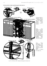
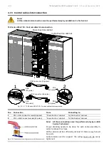
4.7.2
Bus bars interconnection
Note!
All the bus bars interconnection must be performed only by an ABB Service Technician!
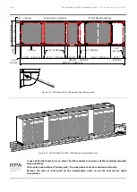
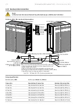
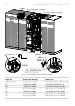
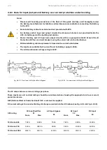
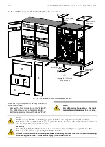
TLE Series 625 & 750 - Bus bars interconnection
Fig. 4.7.2-1 TLE Series 625 & 750 – Bus bars interconnection
Torque Specifications
Bolt size (mm):
M10
Bolt torque:
355 Lb-in / 40 N-m
Connection
Description of connection
Bus bars interconnection
L1 Inverter
Interconnection L1 Inverter
1 Bus bar 60/10 x 270 mm
L2 Inverter
Interconnection L2 Inverter
1 Bus bar 60/10 x 270 mm
L3 Inverter
Interconnection L3 Inverter
1 Bus bar 60/10 x 270 mm
L1 Rectifier
Interconnection L1 Rectifier
1 Bus bar 60/10 x 270 mm
L2 Rectifier
Interconnection L2 Rectifier
1 Bus bar 60/10 x 270 mm
L3 Rectifier
Interconnection L3 Rectifier
1 Bus bar 60/10 x 270 mm
N - Neutral
Interconnection N - Neutral
1 Bus bar 100/10 x 270 mm
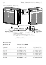
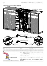
Detail showing bus bars interconnection
Pre Fixed Nut
M10 Flat Washer
M10 Spring Washer
Bolt M10x35
Bus Bar
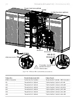
Bus bars interconnection
L1 Inverter
L2 Inverter
L3 Inverter
L1 Rectifier
N - Neutral
L2 Rectifier
L3 Rectifier
Power Section cabinet
Apply UL listed
termination compound
suitable for
copper-to-copper surface
(UL category DVYW)
In/Out Section cabinet
Refer to the Installation Guide attached to the UPS, in particular:
- Verify the presence of oxidation on bare copper bus bars and
scratch it away with a brush;
- Apply the termination compound attached on the joint's side;
- By using a tool, deposit a uniform layer to cover the contact surface;
- Connect the bar and remove any excess of compound.
TLES_UL_625-750
_S2_UPS connectio
n cabinets_ABB_0
2US

