


•
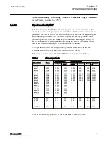
the character ^ in front of an input/output signal name indicates that the
signal name may be customized using the PCM600 software.
•
the character * after an input signal name indicates that the signal must
be connected to another function block in the application configuration
to achieve a valid application configuration.
•
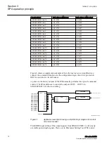
Logic diagrams describe the signal logic inside the function block and are
bordered by dashed lines.
•
Signals in frames with a shaded area on their right hand side represent
setting parameter signals that are only settable via the PST, ECT or
LHMI.
•
If an internal signal path cannot be drawn with a continuous line, the
suffix -int is added to the signal name to indicate where the signal starts
and continues.
•
Signal paths that extend beyond the logic diagram and continue in
another diagram have the suffix ”-cont.”
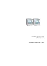
Illustrations are used as an example and might show other products
than the one the manual describes. The example that is illustrated is
still valid.
1MRK 511 418-UEN A
Section 1
Introduction
650 series 2.2 IEC
9
Communication protocol manual


