Videographic Recorders
SM1000 and SM2000
2 Math Configuration
IM/SM2000ADV
Issue 7
17
Mass Flow – Derived density correction
This method uses a preset table of temperature and density
values to define the correction, which is calculated as follows:
Qmd = Qc x density correction
Mass Flow – Measured Density Correction
Qmm = Qc x input from density meter.
Where a3 is the input from an external density meter.
2.10.2 Ideal Gas Flow
Gas flow is usually measured using a differential pressure device
across orifice plates and wedges.
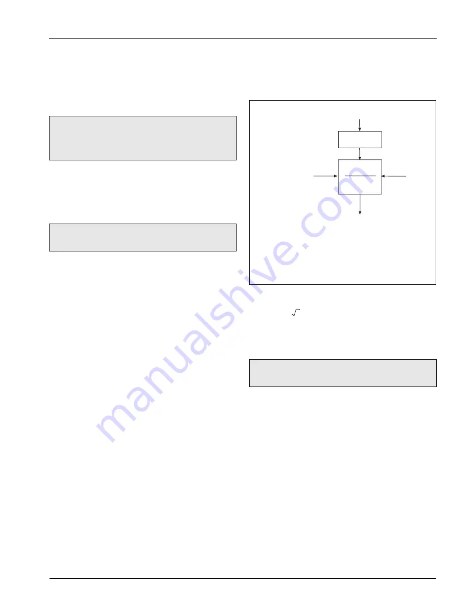
Corrections can be applied to compensate for variations in
temperature and pressure – see Fig. 2.13.
Where
, the square root extraction and scaling can be
achieved on the DP device or on the input set up of the recorder.
Let m1 = constant 1 x a3
Qc = m2 = a1 x constant2 x a2/m1
Note.
Input a3 is the actual product temperature input (as
a2 in previous examples) but with the density correction
applied using a custom linearizer – see Section 4.9.1 of the
User Guide (IM/SM1000 or IM/SM2000).
Note.
With all of the above calculations the engineering
range should allow for the extremes of all the input variables.
m3
a1
a3
scaling factor
×
×
m2
-----------------------------------------------------------
=
m3
a1
a3 m2
⁄
×
m2
-------------------------------
=
Fig. 2.13 Temperature and Pressure Compensation
Note.
The engineering range should allow for the extremes
of all the input variables.
Q
P
ref
x
T
A
x Q
T
ref
x P
A
Q
c
= Corrected Volumetric Flow
Ideal Gas Flow
P
A
T
A
Q
=
Volumetric uncorrected flow
T
ref
=
Reference temperature in K or ºR
T
A
=
Actual temperature in K or ºR
P
ref
=
Reference pressure in Absolute
P
A
=
Actual pressure in Absolute
Q
K h
=


