background image

6

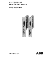
ABB Automation

1MRS 750107-MUM

Serial LonTalk

 Adapter

Technical Reference Manual

SLTA Option Card

3. Functions

3.1.

General

The SLTA option card contains one fibre-optic transmitter/receiver pair and one 
RS232 interface. Both of these communication interfaces are connected to the SLTA 
core module, LTS-20. In addition to this, the fibre-optic pair is connected to the open 
collector bus on the mother board of the RER 111 unit. A message received from the 
RS232 interface is sent to the fibre-optic channel on the option card and the open 
collector bus on the mother board. A message received from the mother board is sent 
to both the fibre-optic transmitter and the RS232 interface.

The SLTA option card also contains a service switch. Pressing this switch generates 
a service pin message. This service pin message is used by the network management 
device (e.g. higher-level processors, PC. etc.) to install and configure the SLTA 
option card. The service pin message is only sent to the L

ON

W

ORKS

 network. It is 

NOT sent to the RS232 interface.

The SLTA option card also contains a service LED. This LED is blinking when the 
SLTA is in the unconfigured state. After configuration of the SLTA option card, the 
LED is off.

The configuration and the use of the SLTA option card requires a host device, for 
example, a PC or a SRIO 1000M. From the host device it is possible to send network 
management commands via the SLTA option card to the L

ON

W

ORKS

 network.

When a PC is used as the host device a network management program and a driver 
have to be installed in the PC. The driver makes enables the network management 
program to send data to the SLTA option card via the RS232 connection with the 
correct protocol (Alert/Ack or buffered link protocol).

The SLTA option card has a self-supervision feature for continuous light reception. 
If the fibre-optic channel receives continuous light, the reception on the channel is 
cut off. The error is notified to the I/O module of the RER 111 LON Star Coupler 
via the error line. Error reset is also notified. For information regarding the error line 
of the RER 111 Star Coupler, refer to the RER 111 manual 1MRS750104-MUM, 
chapter 4.1.

The indication LED of the fibre-optic channel is continuously lit if continuous light 
is received.

3.2.

RS232 interface

The RS232 interface is a 9-pin D-type female connector.

The RS232 interface can be configured to operate as Data Communication 
Equipment (DCE) or Data Terminal Equipment (DTE). This DTE function allows a 
pair of modems to be used and a telephone line to be connected, enabling the 
L

ON

W

ORKS

 network to be controlled from a remote source.

Other user definable parameters are:

- automatic communication speed detection
- user definable communication speeds are 1200, 2400, 9600, 14400, 19200, 
  38400, 57600 and 115200 bits per second.

Содержание SLTA Option Card Serial LonTalk

Страница 1: ...ABB Automation SLTA Option Card Serial LonTalk Adapter Technical Reference Manual ...

Страница 2: ...2 ABB Automation Serial LonTalk Adapter Technical Reference Manual SLTA Option Card ...

Страница 3: ...e 9 5 2 1 Specification 9 5 2 2 3 Wire connection to a host 10 5 2 3 8 Wire connection to a modem 10 5 3 Fibr optic interface 11 5 4 Service switch 11 6 Installation configuration and programming 12 6 1 Installation 12 6 2 Configuration 12 6 2 1 Configuration of the DCE DTE attribute 12 6 2 2 Configuration of autobaud baud rate and other communication parameters 13 6 2 3 Factory default settings 1...

Страница 4: ...n RS232 interface to be connected to the LONWORKS network Physically the RS232 interface is a 9 pin D type female connector The SLTA option card can be connected to a remote host via the telephone network and a pair of modems The SLTA option card also contains a fibre optic transceiver pair of one of the following types ST type glass fibre optic transceiver snap in type plastic fibre optic transce...

Страница 5: ...er PC for example can control the network through an SLTA A SRIO 1000M unit can also be connected to the SLTA option card and have a connection to the LONWORKS network A host device can be connected either directly to the SLTA option card or via the telephone network using a pair of modems LJ 6 VWHP VWUXFWXUH ZKHQ WKH LQWHUIDFH WR WKH KRVW LV LPSOHPHQWHG ZLWK DQ 6 7 Connection to higher level devi...

Страница 6: ...ample a PC or a SRIO 1000M From the host device it is possible to send network management commands via the SLTA option card to the LONWORKS network When a PC is used as the host device a network management program and a driver have to be installed in the PC The driver makes enables the network management program to send data to the SLTA option card via the RS232 connection with the correct protoco...

Страница 7: ...nd are defined by the user in the order For ordering information please see chapter 9 The SLTA option card also contains a LED for the fibre optic receiver This LED flashes when a message is received The fibre optic interface in the SLTA option card has a built in support for collision detection The speed of the fibre optic channel is 1 25 Mbit s only 3 4 LTS 20 core module The Echelon LTS 20 core...

Страница 8: ... mm x 19 8 mm LJ 0HFKDQLFDO VWUXFWXUH RI WKH 6 7 RSWLRQ FDUG RX TX LED Control Logic Continuous light control Internal open collector bus Internal error line Fibre optic interface Control Logic LTS 20 diagnostic LTS 20 SLTA core module RS232 interface RS232 LED Service LED Service PIN S1 Configuration jumpers S2 Configuration jumpers sslta_2 Service Pin Tx Rx 0279C FOC RS232 Service Led RS232 SSLT...

Страница 9: ...al communication cable is limited to max 12 m It is recommended to connect the shield to ground in one end of the cable However depending on the specific case and the surroundings the cable may need more than one earth connection In such a case the other earth connections should be made through a capacitor To connect the protective shield note the following instruction The protective shield is des...

Страница 10: ... for an 8 wire connection to a modem LJ LDJUDP IRU DQ ZLUH FRQQHFWLRQ Protective shield Conductive casing sslta_4 2 2 2 2 3 3 3 3 5 5 5 7 Host DTE Mode SLTA DCE Mode RXD TXD GND RXD TXD GND 9 pin female D connector 9 pin male D connector Host DTE Mode SLTA DCE Mode TXD GND RXD RXD TXD GND 9 pin male D connector 25 pin female D connector sslta_5 1 2 3 4 5 6 7 8 9 1 2 3 4 5 6 7 8 9 Modem DCE Mode SL...

Страница 11: ...1 manual 1MRS750104 MUM chapter 6 2 5 4 Service switch The service switch is used to produce a service pin message This message can then be used by the network management device e g higher level processors PC etc to install and configure the SLTA option card When the switch is pressed and released the SLTA generates a service pin message The service pin message is sent to the LONWORKS network NOT ...

Страница 12: ...H SRZHU VXSSO 3XVK WKH RSWLRQ FDUG LQWR WKH XQLW XQWLO WKH IURQW SODWH LV IOXVK ZLWK WKH UDFN 7LJKWHQ WKH RSWLRQ FDUG RU WKH EODQN SODWH WR WKH FDVH ZLWK WKH VWUDLQ VFUHZV 1RWLFH Do not touch the fibre optic transceiver Do not remove dust shields from transceivers not in use LJ QVWDOODWLRQ RI 6 7 RSWLRQ FDUG LQ WKH 5 5 XQLW 6 2 Configuration 6 2 1 Configuration of the DCE DTE attribute The SLTA op...

Страница 13: ...h a remote host or a local host If the card is connected to a host via a modem link remote state should be selected If no modem is used the jumper should be set for local host state Factory default setting local state XPSHU J4 specifies whether network communication is enabled or disabled after a reset If network communication is disabled then the SLTA option card enters into the FLUSH state after...

Страница 14: ... serial communication rate of the SLTA option card This facility cannot be used in conjunction with autobaud There are eight available bit rates Factory default 9600 bit s 6 2 3 Factory default settings Factory default settings for jumper groups S1 and S2 are as follows XPSHU JURXS 6 DCE mode LJ DFWRU GHIDXOW VHWWLQJV IRU MXPSHU JURXS 6 RQ WKH 6 7 RSWLRQ FDUG XPSHU JURXS 6 Alert Ack protocol Local...

Страница 15: ...ion card is programmed by the manufacturer However the option card has a network address which should be programmed by the user before the card is used in the LONWORKS network The network address consists of a node number and a subnet number A new address will take effect immediately after a change By default the node number is 127 and the subnet number is 1 1RWH If any other parameter value is to...

Страница 16: ...e From the mother board interconnection 8 VDC Power consumption SSLTA C MM option card 1 4 W SSLTA C BB option card 1 4 W Size E1 Card 100 mm x 160 mm Front plate 116 4 mm x 19 8 mm Disturbance tests High frequency interference test according to IEC 60255 22 1 common mode 2 5 kV 1 Mhz differential mode 1 0 kV 1 Mhz Fast transient test according to IEC 61000 4 4 and IEC 60255 22 4 cl 4 4 kV Electro...

Страница 17: ...chnical Reference Manual SLTA Option Card ABB Automation 17 Climatic environmental tests Dry heat test according to IEC 60068 2 2 55 C Dry cold test according to IEC 60068 2 1 10 C Damp heat test according to IEC 60068 2 30 RH 93 55 C 6 cycles ...

Страница 18: ...ing continuous light 8 1 2 RS232 LED The RS232 LED flashes when a message is being received from the RS232 interface i e from the host device 8 1 3 Service LED If the service LED is off the Neuron Chip is in the configured state If the service LED is flashing the Neuron Chip is in the unconfigured state If the service LED is continuously on then the network interface has detected a hardware failur...

Страница 19: ...e 003 3 metre Number of cables The RS232 cable to be used between a modem and the SLTA option card can be ordered separately The type designation of the cable is 1 pc 1MRS120514 xxx2QH VHULDO FRPPXQLFDWLRQ FDEOH EHWZHHQ PRGHP DQG 6 7 RSWLRQ FDUG Cable length 001 1 metre 003 3 metre Number of cables The RS232 cable to be used between a SRIO 1000M and the SLTA option card can be ordered separately T...

Страница 20: ...x02 6 8 set during installation comm_clock 0 0x08 5 input_clock 8 1 25 Mbit s input_clock 5 3 10 Mhz comm_type 1 0x09 3 single_ended comm_pin_dir 0x0E 5 dir mode single_ended preamble_length 6 0x0A 8 240 µs packet_cycle 4 0x0B 8 4 ms beta2_control 0 0x0C 8 xmit_interpacket 0 0x0D 8 recv_interpacket 0 0x0E 8 node_priority 0 0x0F 8 no priority slot allocated channel_priorities 30 0x10 8 number of pr...

Страница 21: ...3150 are U S registered trademarks of Echelon Corporation LonLink LonMark LonSupport LonUsers LonMaker and 3120 are trademarks of Echelon Corporation Revision history Date Versio Revision Author Description 05 01 1998 A T Peltoniemi Original version 29 12 1999 B1 M Kiikkala Update version Q4 99 01 03 2000 B2 M Kiikkala References to SMA transceiver option removed ...

Страница 22: ...22 ABB Automation 1MRS 750107 MUM Serial LonTalk Adapter Technical Reference Manual SLTA Option Card ...

Страница 23: ......

Страница 24: ...ABB Substation Automation Oy P O Box 699 FIN 65101 VAASA Finland Tel 358 10 224 000 Fax 358 10 224 1094 www abb fi 1MRS 750107 MUM EN 05 2000 ...

Отзывы: