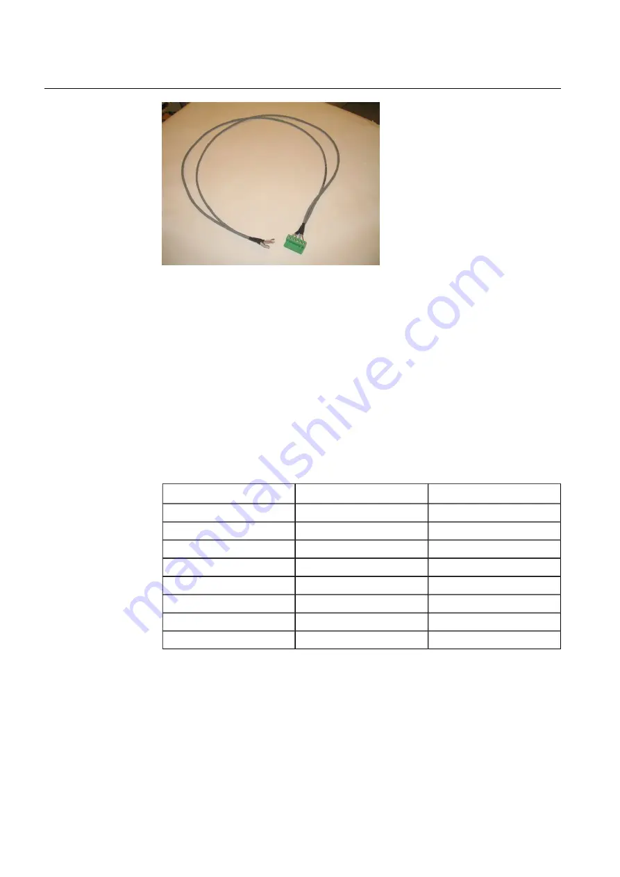
mA_cable2.JPG
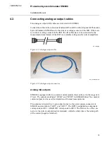
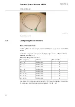
Figure 4.2-3 mA cable
Configuring the connectors
4.3.
Binary I/O connectors
The binary I/O connectors are represented in the IO Editor by components labelled REL
and DI.
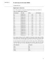
The 16 REL components correspond to the digital output connectors that transfer data
to the IED, see Table 4.3-1.
Table 4.3-1 Binary I/O connectors
I/O connector
I/O cable
REL component
X1
DIGITAL I/O 1
REL 1 - 2
X2
DIGITAL I/O 1
REL 3 – 4
X3
DIGITAL I/O 1
REL 5 – 6
X4
DIGITAL I/O 1
REL 7 - 8
X1
DIGITAL I/O 2
REL 9 - 10
X2
DIGITAL I/O 2
REL 11 – 12
X3
DIGITAL I/O 2
REL 13 – 14
X4
DIGITAL I/O 2
REL 15 – 16
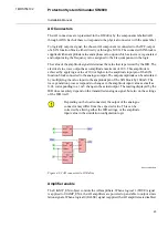
To activate a REL component, apply a logical 1 (TRUE) signal to the input. To deactivate
the component, return the input signal to a logical 0 (FALSE level).
20
1MRS756102
Protection System Simulator SIM600
Installation Manual

