


Mounting
42/14-37-EN Sensyflow
FMT200-D
15
3.4
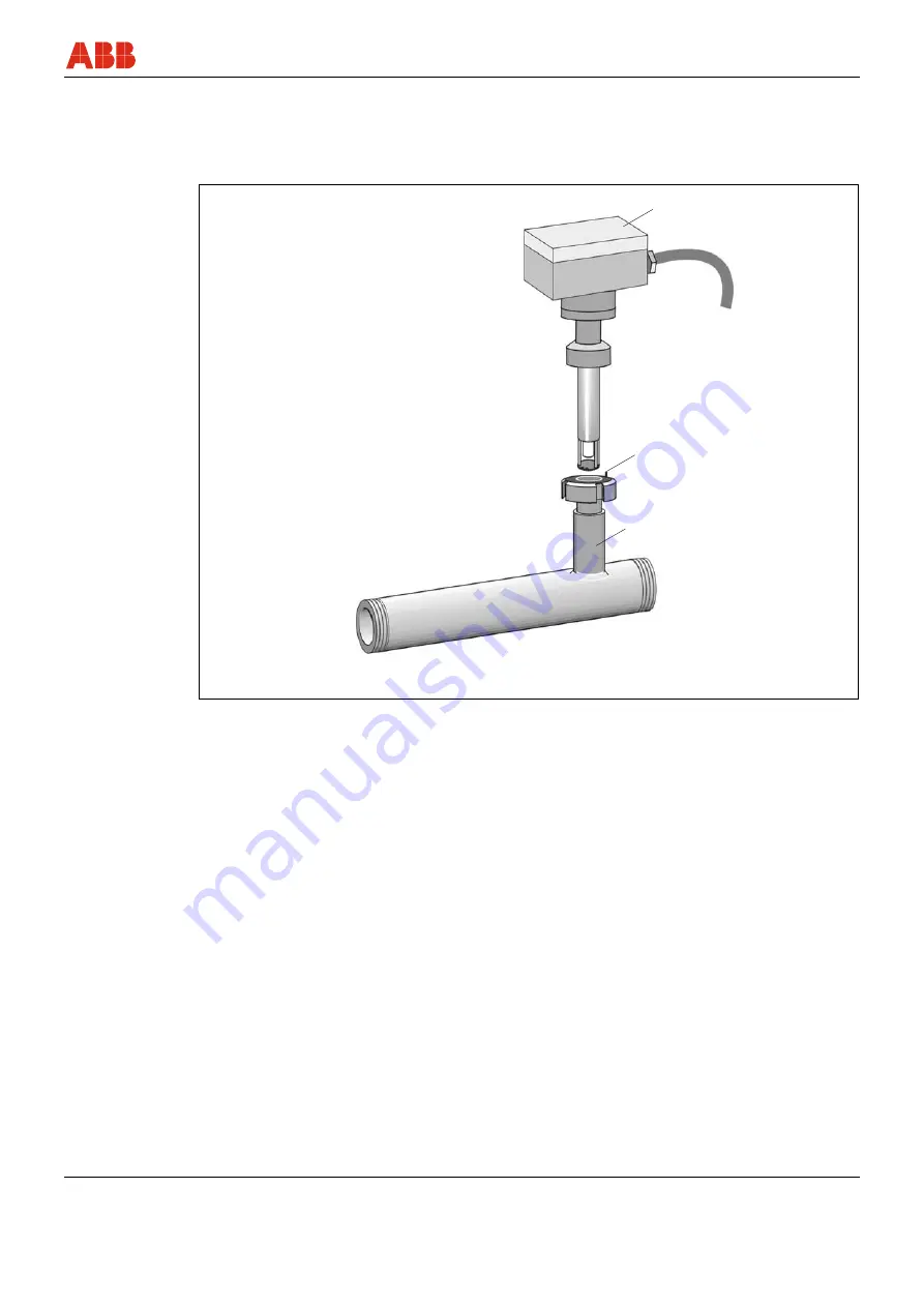
Installing the flowmeter sensor and pipe components
The installation is described using the example of a pipe component. The description
analogously also applies to the installation using a weld-on adapter.
3
1
2
G01035
Fig. 3:
Schematic representation of the pipe component with external thread
1
Flowmeter sensor
2
Centering pin, outflow side
3
Pipe component
• The flow direction must correspond to the arrow indicated on the pipe component.
• The gaskets used must not alter the cross- section of the opening in the pipeline and must
ensure complete tightness once the flowmeter sensor and pipe component have been
installed.
• The centering pin on the pipe component or weld-on adapter must be located on the outlet
side downstream of the measuring point.
• Check the supplied gasket G according to DIN 11851 between the transducer and the pipe
component / weld-on adapter for signs of damage prior to installation.
• When using flange-type pipe components all flange screws must be installed properly.
• Connecting threads are to be connected with the pipelines of the system using suitable
sealant. All screw connections are to be checked for tightness.


