1MRS751802-MUM
REX 521
77
Protection Relay
Technical Reference Manual, Standard Configurations
Fig. 5.2.1.-3
Interlocking using disconnector and/or earth-switch state
Using disconnector, earth-switch and logical inputs
In the cases mentioned above, additional signals, such as SF6 gas low, may be used
to block close operations. Then, these signals should be connected to the
interlocking template using the logic inputs 1...3 (Logic_inpX) selectors. By
selecting “Interlocking_C”, “Interlocking_D” or “Interlocking_E” in the
Close
enable
selector, different AND/ OR conditions can be created.
Examples:
• DC or ES and “Logic_inpX” = “Interlocking_C”
• DC and ES and “Logic_inpX” = “Interlocking_D”
• “Logic_inp1” and “Logic_inp2” and “Logic_inp3” = “Interlocking_E”
In addition to the ones mentioned here, many different kinds of interlocking schemes
can be built by using the selectors to connect digital inputs, inversion to create AND/
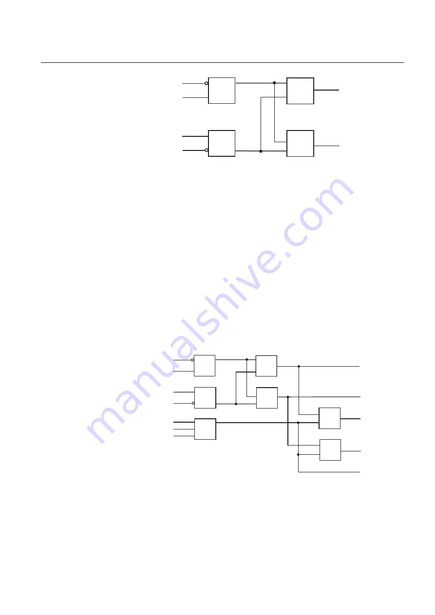
OR logic and selecting different interlocking outputs (A...E). See Fig. 5.2.1.-4 for a
complete block diagram.
Fig. 5.2.1.-4
Interlocking using disconnector, earth-switch and logical inputs
DC pos. open
DC pos. close
&
Interlocking_A
ES pos. open
ES pos. close
&
Interlocking_B
Int
e
rl
3
&
≥
1
DC pos. open
DC pos. close
&
≥
1
Interlocking_A
ES pos. open
ES pos. close
&
Interlocking_B
Int
e
rl
4
&
&
Logic input 1
Logic input 2
Logic input 3
&
&
Interlocking_C
Interlocking_D
Interlocking_E
Содержание REX 521
Страница 1: ...Protection Relay REX 521 Technical Reference Manual Standard Configurations ...
Страница 2: ......
Страница 12: ...12 ...
Страница 22: ...22 ...
Страница 62: ...62 ...
Страница 72: ...72 ...
Страница 128: ...128 ...
Страница 132: ...132 ...
Страница 172: ...172 ...
Страница 198: ...198 ...
Страница 249: ......


