


8.1.3.7
Setting of reach in resistive direction
SEMOD168247-76 v2
Set the resistive reach independently for each zone, and separately for phase-to-phase
(
R1PP
), and phase-to-ground loop (
R1PG
) measurement.
Set separately the expected fault resistance for phase-to-phase faults (
R1PP
) and for
the phase-to-ground faults (
RFPG
) for each zone. Set all remaining reach setting
parameters independently of each other for each distance zone.
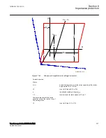
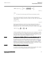
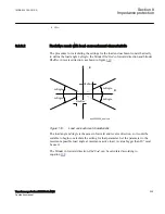
The final reach in resistive direction for phase-to-ground fault loop measurement
automatically follows the values of the line-positive and zero-sequence resistance, and
at the end of the protected zone is equal to equation
1
R
(2 R1P G R0P G) RFP G
3
=
×
+
+
EQUATION1716 V1 EN-US
(Equation 91)
2 X1PE + X0
arctan
2 R1PE + R0
loop
j
é
ù
×
ê
ú
=
×
ê
ú
ë
û
EQUATION1457 V1 EN-US
(Equation 92)
Setting of the resistive reach for the underreaching zone1 must follow the following
condition:
RFP G
4.5 X1P G
£
×
EQUATION1717 V1 EN-US
(Equation 93)
The fault resistance for phase-to-phase faults is normally quite low, compared to the
fault resistance for phase-to-ground faults. Limit the setting of the zone1 reach in
resistive direction for phase-to-phase loop measurement to:
3
1
RFPP
X
£ ×
EQUATION570 V2 EN-US
(Equation 94)
8.1.3.8
Load impedance limitation, without load encroachment function
SEMOD168247-91 v3
The following instructions is valid when the load encroachment function is not
activated, which is done by setting the parameter
Rld
for the Phase Selector to its upper
limit. If the load encroachment function is to be used for all or some of the measuring
zones, the load limitation for those zones according to this chapter can be omitted.
Check the maximum permissible resistive reach for any zone to ensure that there is a
sufficient setting margin between the IED boundary and the minimum load impedance.
The minimum load impedance (Ω/phase) is calculated as:
1MRK 504 163-UUS A
Section 8
Impedance protection
Transformer protection RET670 2.2 ANSI
245
Application manual
Содержание RELION RET670
Страница 1: ...RELION 670 SERIES Transformer protection RET670 Version 2 2 ANSI Application manual ...
Страница 2: ......
Страница 48: ...42 ...
Страница 64: ...58 ...
Страница 74: ...68 ...
Страница 104: ...98 ...
Страница 194: ...188 ...
Страница 518: ...512 ...
Страница 618: ...612 ...
Страница 648: ...642 ...
Страница 666: ...660 ...
Страница 672: ...666 ...
Страница 682: ...676 ...
Страница 844: ...838 ...
Страница 868: ...862 ...
Страница 956: ...950 ...
Страница 964: ...958 ...
Страница 1004: ...998 ...
Страница 1014: ...1008 ...
Страница 1015: ...1009 ...


