


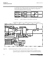


set outside INx>Max and INx>Min, the closest of the limits to INx> is used by the
function. If
INx>Max
is smaller then
INx>Min
, the limits are swapped. The
principle of the limitation is shown in Figure
.
hi
u
lo
y
MIN
MAX
INx>_used
INx>Max
INx>
INx>Min
IEC17000017-1-en.vsdx
IEC17000017 V1 EN-US
Figure 58:
Logic for limitation of used operation current value
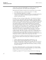
Simplified logic diagram for one residual overcurrent step is shown in Figure
X
Inverse
tx
OR
|I
OP
|
PUSTx
TRSTx
AND
T
F
HarmRestrainx=Disabled
Pickupx
BLKx
BLOCK
OR
2ndHarm_BLOCK_Int
MultPUx
Characteristx=Inverse
Characteristx=DefTime
DirModex=Off
DirModex=Non-directional
DirModex=Forward
DirModex=Reverse
AND
AND
FORWARD_Int
REVERSE_Int
OR
OR
STEPx_DIR_Int
ANSI10000008-4-en.vsd
X
T
F
a
b
a>b
b
a
a>b
IMinx
AND
tMin
BLKTR
AND
EMULTX
ANSI10000008 V3 EN-US
Figure 59:
Simplified logic diagram for residual overcurrent step x, where x = step 1, 2, 3 or 4
The protection can be completely blocked from the binary input BLOCK. Output
signals for respective step, and PUSTx and TRSTx, can be blocked from the binary
Section 8
1MRK 511 408-UUS A
Current protection
204
Phasor measurement unit RES670 2.2 ANSI
Technical manual
Содержание Relion RES670
Страница 1: ...RELION 670 SERIES Phasor measurement unit RES670 Version 2 2 ANSI Technical manual ...
Страница 2: ......
Страница 276: ...270 ...
Страница 306: ...300 ...
Страница 360: ...354 ...
Страница 406: ...400 ...
Страница 614: ...608 ...
Страница 732: ...726 ...
Страница 748: ...742 ...
Страница 884: ...878 ...
Страница 932: ...926 ...
Страница 933: ...927 ...