IEC18000588=ANSI18000588=1=en-us=Original.vsdx
S3
S1
S2
V1
V2
IEC18000588=ANSI18000588=1=en-us=Original.vsdx
S3
S1
S2
V1
V2
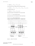
ANSI18000588 V1 EN-US
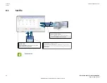
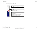
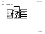
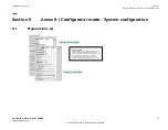
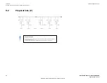
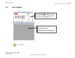
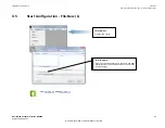
Figure 20: Bay model viewer
Table 10: Function of selections
Selection
Function
S1
Preview of Base bay models(created by ABB)
S2
Preview of User bay models (created by users)
S3
Table of bay models: The content of this table depends on the selection S1/S2.
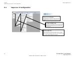
By selecting one table row (one Bay Model) with a left mouse click, the Bay Model
viewer provides a preview of the single-line diagram as well as a short
description.
Table 11: Indications
Selection
Function
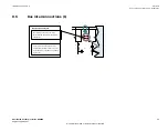
V1
Single-line diagram of the selected BM → Selection made under S3
V2
Description of the selected BM → Selection made under S3
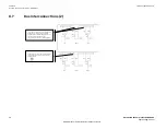
Example:
2SSF5A1
BBP,BFP
2 x single Pole
double busbar, F5A1 → BM identifier
Station protection functions contained in the BM
Tripping outputs configured in the BM → two sets of
single pole trip-ping contacts (2 x 3)
7.7
Operator mode
GUID-F2E37B70-AB2E-4638-93A1-B811142498EB v3
If the HMI500 software is started under the Configurator Mode, the user can change over to the
Operator Mode at any time. The login process is described under
.
Section 7
1MRK 511 452-UUS Rev. A
Tools
40
Distributed busbar protection REB500
Engineering manual
© 2020 Hitachi Power Grids. All rights reserved


