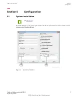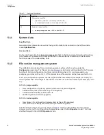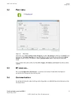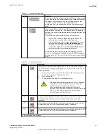
Button
Functions
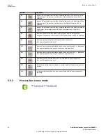
B5
Import a Bay Model from the Bay Model database to the left side of the
selected bay. This button is active only, if the Model Mode (see S2) is
selected.
B6
Import a Bay Model from the Bay Model database to the right side of the
selected bay. This button is active only if the Model Mode (see S2) is
selected.
B7
Import a Bay Model from the Bay Model database to the right end side of
the busbar. This button is active only if the Model Mode (see S2) is
selected.
B8
Remove the selected Bay Model or Bay Figure from the single-line
diagram. This button is active only if the Model Mode (see S2) is selected.
B9
Interconnect two selected adjacent busbar-connectors.
(for special applications only)
B10
Interconnect two selected distant busbar-connectors with →← reference.
(for special applications only, for example, ring busbars)
B11
Interconnect two selected distant busbar-connectors with ←→ reference.
(for special applications only, for example, ring busbars)
B12
Remove interconnection between two selected busbar-connectors.
(for special applications only)
B13
Make the invisible caption of one or several selected busbar-connectors
visible.
B14
Make the visible caption of one or several selected busbar-connectors
invisible
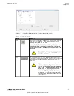
5.5.2
Process bus zones mode
GUID-C405A422-0A43-4B82-8EC8-405520BB4886 v3
Section 5
1MRK 511 452-UUS Rev. A
Configuration
22
Distributed busbar protection REB500
Engineering manual
© 2020 Hitachi Power Grids. All rights reserved


