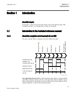
The Technical Reference Manual (TRM)
contains application and functionality
descriptions and it lists function blocks, logic diagrams, input and output signals,
setting parameters and technical data sorted per function. The technical reference
manual should be used as a technical reference during the engineering phase,
installation and commissioning phase, and during normal service.
The Installation and Commissioning Manual (ICM)
contains instructions on how to
install and commission the protection IED. The manual can also be used as a reference
during periodic testing. The manual covers procedures for mechanical and electrical
installation, energizing and checking of external circuitry, setting and configuration as
well as verifying settings and performing directional tests. The chapters are organized
in the chronological order (indicated by chapter/section numbers) in which the
protection IED should be installed and commissioned.
The Operator’s Manual (OM)
contains instructions on how to operate the protection
IED during normal service once it has been commissioned. The operator’s manual can
be used to find out how to handle disturbances or how to view calculated and measured
network data in order to determine the cause of a fault.
The Engineering Manual (EM)
contains instructions on how to engineer the IEDs
using the different tools in PCM600. The manual provides instructions on how to set
up a PCM600 project and insert IEDs to the project structure. The manual also
recommends a sequence for engineering of protection and control functions, LHMI
functions as well as communication engineering for IEC 61850 and DNP3.
1.1.2
About the technical reference manual
The following chapters are included in the technical reference manual.
•
Local HMI
describes the control panel on the IED and explains display
characteristics, control keys and various local HMI features.
•
Basic IED functions
presents functions for all protection types that are included in
all IEDs, for example, time synchronization, self supervision with event list, test
mode and other general functions.
•
Differential protection
describes differential functions and restricted ground fault
protection.
•
Impedance protection
describes functions for distance zones with their
quadrilateral characteristics, phase selection with load encroachment, power swing
detection and similar.
•
Current protection
describes functions, for example, over current protection,
breaker failure protection and pole discordance.
•
Voltage protection
describes functions for under voltage and over voltage
protection and residual over voltage protection.
•
Frequency protection
describes functions for over frequency, under frequency and
rate of change of frequency protection.
Section 1
1MRK505222-UUS C
Introduction
36
Technical reference manual
Содержание Relion 670 series
Страница 1: ...Relion 670 series Line differential protection RED670 ANSI Technical reference manual...
Страница 2: ......
Страница 40: ...34...
Страница 50: ...44...
Страница 60: ...54...
Страница 126: ...120...
Страница 384: ...378...
Страница 496: ...490...
Страница 556: ...550...
Страница 602: ...596...
Страница 620: ...614...
Страница 794: ...788...
Страница 864: ...858...
Страница 988: ...982...
Страница 998: ...992...
Страница 1084: ...1078...
Страница 1164: ...1158...
Страница 1168: ...1162...
Страница 1170: ...1MRK002802 AB 1 670 1 2 PG ANSI V1 EN Section 21 1MRK505222 UUS C Connection diagrams 1164 Technical reference manual...
Страница 1171: ...1MRK002802 AB 2 670 1 2 PG ANSI V1 EN 1MRK505222 UUS C Section 21 Connection diagrams 1165 Technical reference manual...
Страница 1172: ...1MRK002802 AB 3 670 1 2 PG ANSI V1 EN Section 21 1MRK505222 UUS C Connection diagrams 1166 Technical reference manual...
Страница 1173: ...1MRK002802 AB 4 670 1 2 PG ANSI V1 EN 1MRK505222 UUS C Section 21 Connection diagrams 1167 Technical reference manual...
Страница 1174: ...1MRK002802 AB 5 670 1 2 ANSI V1 EN Section 21 1MRK505222 UUS C Connection diagrams 1168 Technical reference manual...
Страница 1175: ...1MRK002802 AB 6 670 1 2 ANSI V1 EN 1MRK505222 UUS C Section 21 Connection diagrams 1169 Technical reference manual...
Страница 1176: ...1MRK002802 AB 7 670 1 2 ANSI V1 EN Section 21 1MRK505222 UUS C Connection diagrams 1170 Technical reference manual...
Страница 1177: ...1MRK002802 AB 8 670 1 2 ANSI V1 EN 1MRK505222 UUS C Section 21 Connection diagrams 1171 Technical reference manual...
Страница 1178: ...1MRK002802 AB 9 670 1 2 ANSI V1 EN Section 21 1MRK505222 UUS C Connection diagrams 1172 Technical reference manual...
Страница 1179: ...1MRK002802 AB 10 670 1 2 ANSI V1 EN 1MRK505222 UUS C Section 21 Connection diagrams 1173 Technical reference manual...
Страница 1180: ...1MRK002802 AB 11 670 1 2 ANSI V1 EN Section 21 1MRK505222 UUS C Connection diagrams 1174 Technical reference manual...
Страница 1181: ...1MRK002802 AB 12 670 1 2 ANSI V1 EN 1MRK505222 UUS C Section 21 Connection diagrams 1175 Technical reference manual...
Страница 1182: ...1MRK002802 AB 13 670 1 2 ANSI V1 EN Section 21 1MRK505222 UUS C Connection diagrams 1176 Technical reference manual...
Страница 1183: ...1MRK002802 AB 14 670 1 2 ANSI V1 EN 1MRK505222 UUS C Section 21 Connection diagrams 1177 Technical reference manual...
Страница 1184: ...1MRK002802 AB 15 670 1 2 ANSI V1 EN Section 21 1MRK505222 UUS C Connection diagrams 1178 Technical reference manual...
Страница 1220: ...1214...
Страница 1230: ...1224...
Страница 1231: ...1225...

