1.
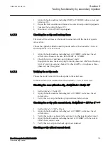
Apply single-phase voltage below the set value
U1>
.
2.
Slowly increase the voltage until the ST1 signal appears.
3.
Note the operate value and compare it with the set value
U1>
.
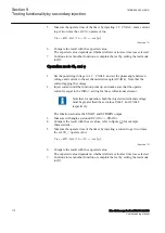
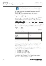
The operate value in secondary volts is calculated according
to the following equations:
For phase-to-earth measurement:
U
UBase VT
VTprim
1
100
3
>
×
×
sec
IECEQUATION2426 V1 EN-US
(Equation 88)
For phase-to-phase measurement:
U
UBase
VT
VTprim
1
100
>
×
×
sec
IECEQUATION2427 V1 EN-US
(Equation 89)
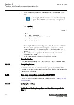
4.
Decrease the voltage slowly and note the reset value.
5.
Set and apply about 20% higher voltage than the measured operate value for
one phase.
6.
Measure the time delay for the TR1 signal and compare it with the set value.
7.
Check the inverse time delay by injecting a voltage corresponding to 1.2 ×
U1>.
8.
Repeat the test to check the inverse time characteristic at different over-
voltage levels.
9.
Repeat the above described steps for Step 2 of the function.
9.5.2.2
Extended testing
GUID-BE4B4A36-CCEE-4020-B7DC-6A83A43D11F5 v2
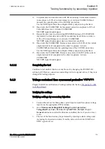
1.
The tests above can be repeated for
2 out of 3
and for
3 out of 3
operation
mode.
9.5.2.3
Completing the test
M13806-43 v6
Continue to test another function or end the test by changing the
TESTMODE
setting to
Off
. Restore connections and settings to their original values, if they were
changed for testing purposes.
9.5.3
Two step residual overvoltage protection ROV2PTOV
SEMOD54358-3 v7
Prepare the IED for verification of settings outlined in Section
.
1MRK 506 383-UEN A
Section 9
Testing functionality by secondary injection
Line distance protection REL650 2.2 IEC
125
Commissioning manual
Содержание REL650 series
Страница 1: ...RELION 650 SERIES Line distance protection REL650 Version 2 2 Commissioning manual...
Страница 2: ......
Страница 24: ...18...
Страница 28: ...22...
Страница 38: ...32...
Страница 54: ...48...
Страница 58: ...52...
Страница 178: ...172...
Страница 182: ...176...
Страница 188: ...182...
Страница 196: ...190...
Страница 206: ...200...
Страница 207: ...201...

