49
Configuring the short range fibre optical
modem
&KDSWHU
&RQILJXULQJWKHGLJLWDO
FRPPXQLFDWLRQPRGXOHV
&RQILJXULQJWKHVKRUWUDQJHILEUHRSWLFDOPRGHP
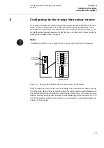
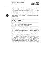
No setting is available for the short range fibre optical modem on the HMI. There are
however some settings that can be made on a DIP-switch located behind the cover
around the fibre optic connectors at the back of the terminal according to figure
. Af-
ter the fibres has been disconnected, if attached, the cover plate can be removed just by
pulling at the middle of the cover plate.
)LJXUH 6HWWLQJDQGLQGLFDWLRQVIRUWKHVKRUWUDQJHRSWLFDOPRGHP
Switch 3 and 4 are used to set the source of timing. The function is according to setting
of timing signal, table
. When using the modem for optical point-to-point transmission,
one modem should be set for locally created timing and the other for timing recovered
from received signal. When the modems are communicating with a transceiver 21-15X
or 16X the modems shall be set for timing recovered from received optical signal, see
setting of timing signal.
1RWH
,IKDQGOHGFDUHIXOO\WKHFRYHUSODWHFDQEHUHPRYHGDOVRZLWKWKHILEUHVDWWDFKHG
Fibre optic
connectors
Cover
plate
On
Off
TXD
CTS
RTS
MA
LA
Sync
RXD
DSR
DCD
RA
LO
Sync
1
2
3
4
Reset
xx00000552.vsd
Содержание REL 551 2.3 Series
Страница 16: ...10 Note signs KDSWHU 6DIHW LQIRUPDWLRQ ...
Страница 44: ...38 Checking the binary I O circuits KDSWHU KHFNLQJ WKH H WHUQDO FLUFXLWU ...
Страница 52: ...46 Checking the self supervision signals KDSWHU QHUJLVLQJ WKH WHUPLQDO ...
Страница 132: ...126 Two step time delayed phase overcurrent protection TOC2 KDSWHU 9HULI LQJ VHWWLQJV E VHFRQGDU LQMHFWLRQ ...
Страница 136: ...130 Testing the interaction of the distance protection KDSWHU 9HULI LQJ WKH LQWHUQDO FRQILJXUDWLRQ ...
Страница 140: ...134 Testing the interaction of the distance protection KDSWHU 7HVWLQJ WKH SURWHFWLRQ V VWHP ...


