116
Scheme communication logic for residual
overcurrent protection (EFC)
Chapter 5
Current
4
Scheme communication logic for residual
overcurrent protection (EFC)
4.1
Application
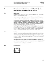
The EFC directional comparison function contains logic for blocking overreaching and permis-
sive overreaching schemes. The function is applicable together with a directional residual over-
current protection in order to decrease the total operate time of a complete scheme.
One communication channel, which can transmit an on / off signal, is required in each direction.
It is recommended to use the complementary additional communication logic EFCA, if the weak
infeed and/or current reversal conditions are expected together with permissive overreaching
scheme.
4.2
Functionality
The communication logic for residual overcurrent protection contains logics for blocking over-
reach and permissive overreach schemes.
In the blocking scheme a signal is sent to the remote end of the line if the directional element, in
the directional residual overcurrent protection (sending end), detects the fault in the reverse di-
rection. If no blocking signal is received and the directional element, in the directional residual
overcurrent protection (receiving end), detects the fault in the forward direction, a trip signal will
be sent after a settable time delay.
In the permissive overreach scheme a signal is sent to the remote end of the line if the directional
element, in the directional residual overcurrent protection (sending end), detects the fault in the
forward direction. If an acceleration signal is received and the directional element, in the direc-
tional residual overcurrent protection (receiving end), detects the fault in the forward direction,
a trip signal will be sent, normally with no time delay. In case of risk for fault current reversal
or weak end infeed, an additional logic can be used to take care of this.
4.3
Function block
xx00000204.vsd
EFC--
EFC
BLOCK
CACC
CSPRM
CSBLK
CR
TRIP
CS
CRL
Содержание REL 501-C1 2.5
Страница 1: ...Technical reference manual Line distance protection terminal REL 501 C1 2 5 ...
Страница 2: ......
Страница 26: ...14 Introduction to the technical reference manual Chapter 1 Introduction ...
Страница 42: ...30 Technical data Chapter 2 General ...
Страница 66: ...54 Blocking of signals during test BST Chapter 3 Common functions ...
Страница 142: ...130 Time delayed overvoltage protection TOV Chapter 6 Voltage ...
Страница 162: ...150 Autorecloser AR Chapter 9 Control ...
Страница 163: ...151 About this chapter Chapter 10 Logic Chapter 10 Logic About this chapter This chapter describes the logic functions ...
Страница 174: ...162 Event function EV Chapter 10 Logic ...
Страница 210: ...198 Serial communication Chapter 12 Data communication ...
Страница 226: ...214 Serial communication modules SCM Chapter 13 Hardware modules ...
Страница 227: ...215 Chapter 14 Diagrams Chapter 14 Diagrams This chapter contains the terminal diagrams for the terminal ...
Страница 229: ...217 Terminal diagrams Chapter 14 Diagrams 1 2 Terminal diagram REL 501 C1 Figure 86 REL 501 C1 ...
Страница 230: ...218 Terminal diagrams Chapter 14 Diagrams Figure 87 REL 501 C1 with DC switch ...
Страница 234: ...222 Terminal diagrams Chapter 14 Diagrams ...
Страница 237: ......


