background image

Feeder Terminal

REF 542plus

1MRS756269

12

Technical data

Measurements

The REF 542plus uses the same analog inputs 
both for measurements and protections.     

Protection functions

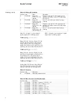
Table 1: Measurements

Quantity

Class

Range

Phase current, earth current

0.5

0.1 - 4 x I

n

Line voltage, phase voltage

0.5

0.2 - 1.5 x U

n

Active, reactive energy

2

-

Active, reactive, apparent power

1

-

Cos 

ϕ

1

0  -  1

Frequency

0.02

-

Table 2: Protection functions and operation time

Quantity

Range

Protection functions

Class 3

Operation time

Class 3 or minimum ±15 ms

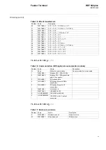
Table 3: Current and voltage transformer input values

Quantity

Range

Rated current I

n

0.2 A, 1.0 A, 5.0 A

Rated voltage U

n

100 - 125 V AC

Rated frequency f

n

50 Hz/60 Hz

Table 4: Thermal load capacity

Quantity

Range

Current path

250 x I

n

 (peak value), 

100 x I

n

 for 1 s (dynamic ), 

5 x I

n

 (continuous)

Voltage path

2 x U

n

/

3 (continuous)

Table 5: Consumption

Quantity

Range

Current path

<0.1 VA at I

n

Voltage path

<0.25 VA at U

n

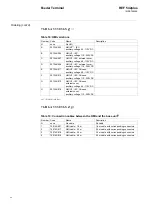
Table 6: ANSI code protection functions and parameters

Current protection functions

68

Inrush stabilization (Only in 
connection with 50 and 51)

N = 2.0 - 8.0
M = 3.0 - 4.0
Time = 200 -100 000 ms

68

Inrush harmonic

Minimum current threshold = 0.05 - 40.00 x I

n


Fault current threshold = 0.05 - 40.00 x I

n

Harmonic ratio threshold = 5 - 50% 

50

Overcurrent instantaneous

I>>> = 0.100 - 40.000 x I

n

t = 15 - 30 000 ms

51

Overcurrent high

I>> = 0.05 - 40.00 x I

n

t = 20 - 300 000 ms

51

Overcurrent low

I> = 0.05 - 40.00 x I

n

t = 20 - 300 000 ms

51 IDMT

Overcurrent IDMT (Inverse Definite 
Minimum Time)

Inverse time characteristics: Normal, Very, Extreme 
and Long-time inverse
I

e

 = 0.050 - 40.000 x I

n

K = 0.050 - 1.500

Содержание REF 542plus

Страница 1: ...Feeder Terminal Product Guide REF 542plus...

Страница 2: ......

Страница 3: ...sensors Optional analog input module 4 20 mA Optional analog output module 0 4 20 mA Optional communication module for the substation automation system Ethernet interface for embedded web server Optic...

Страница 4: ...or or in a dedi cated compartment close to the base unit The HMI can be used to set the protection parameters to locally operate the switching devices in the switchgear and to visualize events and mea...

Страница 5: ...1062 The same software is also used to define the protection and the control scheme A050399 Fig 5 HMI control unit The left side of the LCD display is reserved for the single line diagram The right si...

Страница 6: ...icenses The licenses are Basic Low Basic Multi Low Multi Differential and Distance In table 20 the corresponding provided pro tection functions are listed Current protection inrush blocking 68 overcur...

Страница 7: ...a sampling rate of 1 2 kHz for a time interval of at least 1 second and for a maximum of 5 seconds The recording time is a combination of pre and post fault time The total recording capability is 5 s...

Страница 8: ...control and interlocking in the switchgear primary objects status acquisition for example circuit breaker in opened closed position circuit breaker spring supervision when applicable Binary inputs are...

Страница 9: ...can additionally in clude another binary input and output module alternatively the communication module or the 0 4 20 mA analog output module Note The backplane for the 0 4 20 mA ana log output module...

Страница 10: ...ig 8 shows an example of wide housing base unit installation inside a low voltage compartment A051270 Fig 8 Base unit installation in LV compartment of a GIS system 10 233 5 18 M4 97 5 97 5 M4 106 3 1...

Страница 11: ...ed in the Fig 9 below The upper one is the version of the HMI without cover and the lower one is with cover to achieve a better protection A051271 A070119 Fig 9 HMI dimensions The advisable panel cut...

Страница 12: ...ble 4 Thermal load capacity Quantity Range Current path 250 x In peak value 100 x In for 1 s dynamic 5 x In continuous Voltage path 2 x Un 3 continuous Table 5 Consumption Quantity Range Current path...

Страница 13: ...In t 100 10 000 ms Angle alpha 0 0 20 0o Angle delta 180 0o 180 0o U0 0 05 0 70 x Un 67N Sector Earth fault directional sector 10 thresholds available Direction enable disable directional behavior Sta...

Страница 14: ...s 0 05 0 30 x In start value of the negative phase sequence K 0 5 30 0 t Reset 0 2000 s Timer decreasing rate 0 100 37 Low load Pn 50 100 000 kW primary values Minimal load P 5 00 x Pn Minimal current...

Страница 15: ...values t 20 10 000 ms Angle delta 1 45 00 0 00 Angle delta 2 90 00 135 00 t 20 10 000 ms 1 non directional stage t 20 10 000 ms Power quality functions Power factor controller Switching sequence line...

Страница 16: ...hot 0 04 1000 s Dead time1st shot 0 10 1000 s Specific operation time 2nd shot 0 04 1000 s Dead time 2nd shot 0 10 1000 s Specific operation time 3rdshot 0 04 1000 s Dead time 3rd shot 0 10 1000 s Spe...

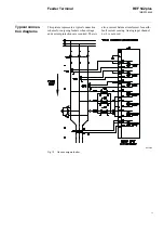
Страница 17: ...is picture represents a typical connection scheme for outgoing feeders when voltage and current protections are required There is also a current balance transformer for earth fault current sensing Ana...

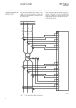
Страница 18: ...g input board has 8 inputs for currents Channels 1 6 are for the differential protection channel 7 is used for the restricted earth fault protection and channel 8 for the earth fault protection A05128...

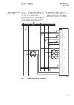
Страница 19: ...to earth volt age measurements and protection of the incoming feeder Channel 7 is used for the residual current for earth fault protection and channel 8 is used for the busbar phase to phase voltage t...

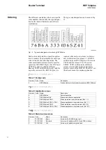
Страница 20: ...rsion V4D02 ATEX certified units with these release version will be delivered with the former version of the HMI V4 The DNV cer tification is meant for marine application 7 6 B 6 A 3 3 3 03 6 S Z 4 1...

Страница 21: ...802 Static I O without control continuity check Static I O without control continuity check 5 750132 801 Binary I O3 20 90 V 14 V DC standard Standard version with 14 V DC treshold value for applicati...

Страница 22: ...standard Standard version with 72 V DC treshold value for application in auxiliary circuit with DC voltage range 80 250 V DC E 750132 806 Binary I O3 80 250 V 72 V DC with static channel As no D one s...

Страница 23: ...1 750170 827 3 CT 3 CT 1 CT 1 CT 42 750170 828 3 CT 3 CT 1 CT 1 VT 43 750170 824 3 CT 3 VT 1 CT 1 CT Table 16 Communication With optional coomunication module Number Code Name Description N None Witho...

Страница 24: ...HMI V5 IEC Chinese auxiliary voltage 48 110V DC F 007346 012 HMI V5 IEC Chinese auxiliary voltage 110 220V DC G 007346 015 HMI V5 IEC Chinese external cover auxiliary voltage 48 110V DC H 007346 016 H...

Страница 25: ...2 Software base license Software level Base 2 1MRS090003 Software high license Software level High 3 1MRS090004 Software basic low license Software level Basic Low 4 1MRS090005 Software basic license...

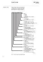
Страница 26: ...n 1 Modbus SPA RS485 2 Modbus SPA glass fibre ST connector For more information see Table 16 Analog input 01 Sensors 10 17 Mixed sensors and transformers 30 43 Mixed transformers For more information...

Страница 27: ...on Functions Configuration and Settings 1MRS755860 Communication Manual Part 4 1VTA100005 Modbus RTU Technical Reference 1MRS755868 Configuration and Operating Tool User s Guide 1MRS755871 IRIG B Inpu...

Страница 28: ...ABB Oy Distribution Automation P O Box 699 FI 65101 Vaasa FINLAND Tel 358 10 22 11 Fax 358 10 224 1094 www abb com substationautomation...

Отзывы: