


1MRS 750500-MUM
)HHGHU7HUPLQDODQG0DFKLQH7HUPLQDO
Operator’s Manual
5(BB
11
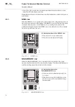
&RQWUROSRVLWLRQEXWWRQ
The control position button [R\L] is used for selecting a control mode according to
the following table. For password handling, refer to section “Passwords” on page 15.
When the control mode is changed with the [R\L] button, the selected control
position is stored.
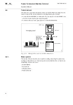
(QWHU
User level:
• entering the MAIN MENU at technical level from the
MIMIC view at user level (by pressing [E] for 2 s and by
entering the password if required)
Technical level:
• entering the MIMIC view at user level from the MAIN
MENU at technical level (by pressing [E] for 2 s)
• activating the setting mode of a parameter in the
parameter menu
• confirming a setting
7DEOH 3XVKEXWWRQIXQFWLRQV
E
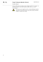
7DEOH &RQWUROSRVLWLRQEXWWRQ
/2&$/
• LOCAL mode is indicated by the yellow [L] LED
indicator
• Objects can be controlled with the [O] and [I]
buttons
• Any remote control signal via serial
communication is inhibited
• Digital input and logic controls are valid
5(027(
• REMOTE mode is indicated by the yellow [R]
LED indicator
• Objects can be controlled remotely via serial
communication
• All local push-buttons are inhibited
• Digital input and logic controls are valid
',6$%/('
• DISABLED mode is indicated with all LED
indicators being off
• Local and remote operations are inhibited
• Digital input and logic controls are valid
/2*,&
• LOGIC mode is indicated with the unmarked
LED indicator being lit
• Digital inputs of the COLOCAT function and
PLC logic are used to select between the
LOCAL, REMOTE and DISABLED modes
• Digital input and logic controls are valid
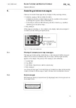
',6$%/('
PRGH
• DISABLED mode is enabled
/2&$/PRGH
• LOCAL mode is enabled
• REMOTE mode is disabled
R
L
R L
R
L
R L
R
L
R L
R
L
R L
R
L
R L
R
L
R L
Содержание REF 54 Series
Страница 1: ...5 B HHGHU 7HUPLQDO 5 0 B 0DFKLQH 7HUPLQDO 2SHUDWRU V 0DQXDO...
Страница 2: ......
Страница 33: ......
Страница 34: ......
Страница 35: ......