


The requirement is now according to equation
.
step1
0
I
1.2 3I (remote busbar with one line out)
³
×
EQUATION1200 V3 EN
(Equation 39)
A higher value of step 1 might be necessary if a big power transformer (Y0/D) at remote
bus bar is disconnected.
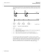
A special case occurs at double circuit lines, with mutual zero-sequence impedance
between the parallel lines, see figure
ANSI05000152_2_en.vsd
One phase-to-ground fault
67N
0
3I
ANSI05000152 V2 EN
Figure 48:
Step 1, third calculation
In this case the residual current out on the line can be larger than in the case of ground fault
on the remote busbar.
step1
0
I
1.2 3I
³
×
EQUATION1201 V3 EN
(Equation 40)
The current setting for step 1 is chosen as the largest of the above calculated residual
currents, measured by the protection.
Step 2
This step has directional function and a short time delay, often about 0.4 s. Step 2 shall
securely detect all ground faults on the line, not detected by step 1.
1MRK 511 286-UUS A
Section 6
Current protection
115
Application manual
Содержание REC650 ANSI
Страница 1: ...Relion 650 series Bay control REC650 ANSI Application manual...
Страница 2: ......
Страница 26: ...20...
Страница 66: ...Section 3 1MRK 511 286 UUS A REC650 setting examples 60 Application manual...
Страница 71: ...IED IED ANSI05000460 V2 EN 1MRK 511 286 UUS A Section 4 Analog inputs 65 Application manual...
Страница 82: ...76...
Страница 92: ...86...
Страница 170: ...164...
Страница 176: ...170...
Страница 274: ...268...
Страница 288: ...282...
Страница 350: ...344...
Страница 369: ...363...


