


4.3 AUXILIARY OPEN (KM1005 Pins 5 and 6)
The Auxiliary Open function is the same as the Remote Open function with the exception of
the input impedance which is approximately 300 kOhms.
4.4 SAFE OPEN (KM1005 Pins 5 and 6)
The Safe Open input is connected to the same pins as Step 4.3 above. It is programmed as
either mode via a dip switch. This input functions as all open inputs above, with the exception
that it has maximum priority over all other inputs.
4.5 PROTECTION TRIP (KM1005 Pins 7 and 8)
The Protection Trip input is designed to work at a lower threshold of 7 VDC. This input is
provided to use with special protection relay requirements. It can also be used as a normal
trip input. It is programmed via Jumper JP1001 Pins 1 and 2 or as a normal input by
jumpering JP1001 pins 2 and 3.
4.6 SECOND TRIP (KM1005 Pins 7 and 8)
The Second Trip is often referred to as “Shunt Trip.” It functions the same as the Remote Input
with the exception of the input impedance which is 300 kOhms.
4.7 CIRCUIT BREAKER LOCKED OPEN (KM1005 Pins 11 and 12)
The Circuit Breaker Locked Open feature functions like the familiar 69 switch. The circuit is
activated when the external trip handle is moved from its normal position (i.e., in the trip
position). In this position the breaker cannot be either locally or remotely closed.
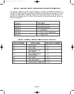
4.8 UNDER VOLTAGE TRIP (KM1005 Pins 13 and 14)
The Under Voltage Trip input will perform an auto trip in the event the voltage source being
monitored, by this input, falls between 35% to 70% of nominal. It is enabled through DIP
Switch I1104/2-3-4. The response of this input also has a programmable time delay from 50
milliseconds to 5 seconds. The delay is set by the various combinations of DIP Switch
I1004/2-3-4. The Under Voltage Threshold is set by I1001. See Table below.
Page 33
DIP SWITCH I1001 POSITION
THRESHOLD
1
100 – 127 VAC/DC
2
48 – 60 VDC
3
24 – 30 VDC
NONE
220 – 240 VAC/DC
38-929M-15A 10/15/02 1:11 PM Page 37
Содержание R-MAG Series
Страница 1: ...Instructions for Vacuum Circuit Breaker Type ABB R MAG OVB DCM 15 5 kV 1250 2000 3000 A 38 929M 15A ...
Страница 2: ...38 929M 15A 10 15 02 1 11 PM Page 2 ...
Страница 4: ...38 929M 15A 10 15 02 1 11 PM Page 4 ...
Страница 15: ...Page 11 Figure 3 Interrupter Assembly 1200 A 38 929M 15A 10 15 02 1 11 PM Page 15 ...
Страница 16: ...Page 12 Figure 4 Interrupter Assembly 2000 A 38 929M 15A 10 15 02 1 11 PM Page 16 ...
Страница 17: ...Page 13 Figure 5 Interrupter Assembly 3000 A 38 929M 15A 10 15 02 1 11 PM Page 17 ...
Страница 19: ...Figure 7 Contact Travel and Over Travel Adjustment Page 15 1 687 38 929M 15A 10 15 02 1 11 PM Page 19 ...
Страница 20: ...Figure 8 Trip Handle Page 16 38 929M 15A 10 15 02 1 11 PM Page 20 ...
Страница 21: ...Figure 9 High Voltage Cabinet Layout Page 17 38 929M 15A 10 15 02 1 11 PM Page 21 ...
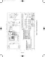
Страница 22: ...Figure 10 Typical Schematic Diagram Page 18 38 929M 15A 10 15 02 1 11 PM Page 22 ...
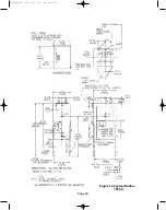
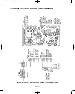
Страница 23: ...Figure 11 Typical Connecting Diagram Page 19 38 929M 15A 10 15 02 1 11 PM Page 23 ...
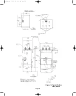
Страница 24: ...Figure 12 Typical Outline 1200 A Page 20 38 929M 15A 10 15 02 1 11 PM Page 24 ...
Страница 25: ...Figure 13 Typical Outline 2000 3000 A Page 21 38 929M 15A 10 15 02 1 11 PM Page 25 ...
Страница 30: ...Page 26 38 929M 15A 10 15 02 1 11 PM Page 30 ...
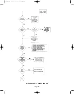
Страница 44: ...Page 40 ILLUSTRATION 8 READY LED OFF 38 929M 15A 10 15 02 1 11 PM Page 44 ...
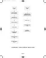
Страница 45: ...Page 41 ILLUSTRATION 9 CB WILL EITHER NOT OPEN OR CLOSE 38 929M 15A 10 15 02 1 11 PM Page 45 ...
Страница 55: ...38 929M 15A 10 15 02 1 11 PM Page 55 ...


