Operation Manual / Power2 340-H / Low-pressure stage
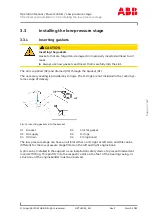
3 Removal and installation / 3.3 Installing the low-pressure stage
© Copyright 2022 ABB. All rights reserved.
HZTL4053_EN
Rev.F
March 2022
3.3.2
Placing the low-pressure stage on the bracket and
aligning
The screws for attaching the low-pressure stage are not included in the Turbo Systems
scope of delivery. Ensure the following:
¡
Strength class 10.9 / 12.9
¡
Use in accordance with DIN EN ISO 898 Part 1
¡
Lightly oiled thread.
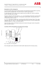
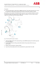
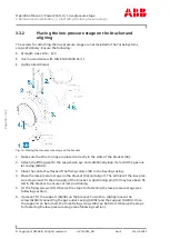
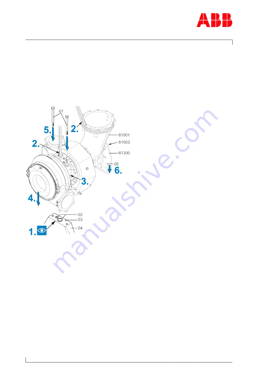
Fig. 14: Placing the low-pressure stage on the bracket
1. Make sure that the O-rings are placed correctly in the slots of the bracket (04).
2. Attach the lifting gear to the suspension eye and additionally loop it around the gas out-
let casing (61001).
3. Clean the contact surfaces of the fixing screws (01) in the bearing casing.
4. Place the low-pressure stage on the bracket (04) and align it. The oil inlet of the low-pres-
sure stage must fit the oil supply of the bracket. A positioning pin (03) may have been fit-
ted in the bracket to ensure correct positioning.
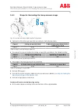
5. Fit the fixing screws (01). Observe the steps for fastening the low-pressure stage (see
following section).
6. If present, fit the support (61300) on the bracket. To do this, slightly loosen the
screw (61003) connecting the gas outlet casing (61001) and the support (61300). Once
the support can be turned, the three fixing screws (05) can be fitted. Observe the steps
for fastening the low-pressure stage (see following section).
Page
34
/
122
Содержание PT003888
Страница 2: ......

