QUICK START GUIDE
Page 4
© 2021 ABB. All rights reserved.
Warning: Shock Hazard and Equipment Damage
-
Equipment and subassembly ports
1.
are suitable for connection to intra
-
building or unexposed wiring or cabling;
2.
can be connected to shielded intra
-
building cabling grounded at both ends.
Step 7
-
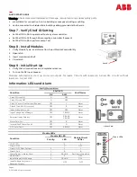
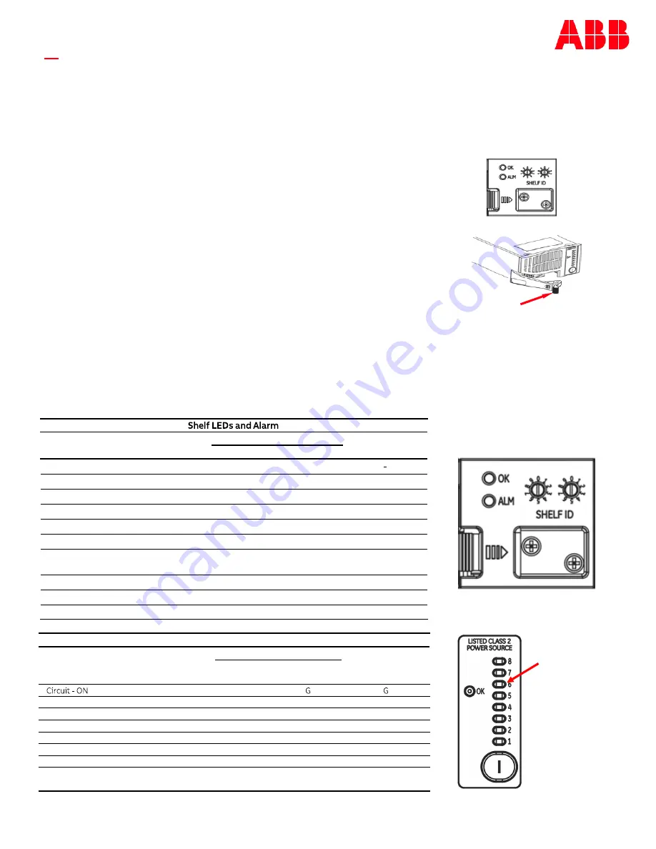
Verify Shelf ID Setting
•
Set Shelf ID to 00 to operate without a system controller.
•
Set Shelf ID to 01 through 98 are read by a controller if present.
•
Set Shelf ID to 99 to perform Lamp Test.
Step 8
-
Install Modules
1.
Verify Module Type
-
see Information: 8 port Module Compatibility
2.
Open latch.
3.
Insert module into Shelf.
4.
Close latch.
Step 9
-
Initial Start Up
1.
Verify that all connections are complete and secure.
2.
Turn on the DC input breaker.
Modules automatically start up and scan outputs for loads. Circuits with loads are turned ON, circuits without
loads are turned OFF.
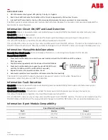
Information: LEDs and Alarm
Latch
Condition
Shelf LED
Shelf Alarm
OK
ALM
Class 2 Circuit ON
G
OFF
Class 2 Circuit OFF
G
OFF
-
Class 2 Circuit Over Current/Shorted
OFF
Y
Alarm
Class 2 Circuit Fail (1 or more)
OFF
R
Alarm
Input Voltage Very Low
OFF
OFF
Alarm
Input Voltage Out of Range
OFF
Y BLINK
Alarm
Reversed Input Polarity
OFF
R BLINK
Y BLINK
Alarm
Alarm Card Fail
OFF
R
Alarm
Internal Shelf Comm Fault3
OFF
G
Alarm
GP Comm Fault
OFF
R BLINK
Alarm
Alarm Card
Module LEDs
Condition
Module OK LED
Module Circuit
LEDs
2
Priority
1
LED
Circuit
-
OFF
G
OFF
Circuit
-
ON
-
Over Current
3
Y
Y
Circuit
-
Fail
1
R
R
Comm Fault <
-
> Alarm Card
4
R BLINK
Per Circuit Condition
Module Fail
1
R
OFF
Input Voltage Out of Range
2
Y BLINK
OFF
Input Voltage Very Low or
Reversed Polarity
OFF
OFF
Circuit LEDs

