


PCS100 AVC-20
User Manual
95
—
11
WIRING
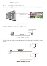
The PCS100 AVC-20 utility supply (input) and load (output) connections are connected directly to the Injection
Transformer terminals in the Transformer Enclosure(s).
The following table defines connection sides.
Transformer terminals
Connection
Top terminals
Utility Supply (Input)
Bottom Terminals
Load (Output)
Table 11
-
1: PCS100 AVC
-
20 power terminals
Figure 11-1 and Figure 11-2 below show power connection location on frame sizes 1B (single enclosure system) and
4B system (example of system with separate Transformer Enclosure).
Refer to section 17.6
for termination details in different frame sizes.
If it is required that the utility supply is connected “Bottom Input” to the bottom transformer terminations, then
the power cables which connect the Auxiliary Circuit Breaker to the transformer top terminations, must be moved
to the transformer bottom terminations.
When utility supply cables are connected “Bottom Input” the load cable terminations are then on top transformer
terminals.
Refer to the document 2UCD280000E003 PCS100 AVC-20 Installation Checklist for more information.
Figure 11
-
2: PCS100 AVC
-
20 frame size 4B Transformer Enclosure
Utility Supply (Input) Terminals
Load (Output) Terminals
Figure 11
-
1: PCS100 AVC
-
20 frame size 1B