background image

10

MOTOR I ZE D SWITCH - DI SCON N EC TOR S , OTM3 20 0 E 4M 2 3 0C- G E

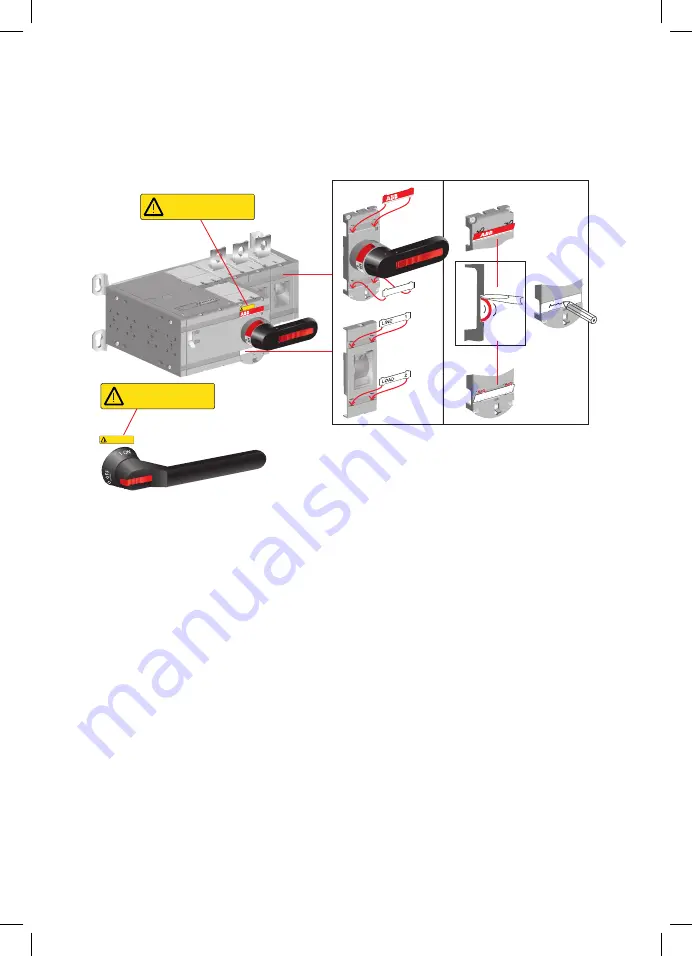
Figure 3.8 

Labelling of the motorized switch-disconnectors

— 

3.7  Labelling

M

M

Man.

Man.

A0

7009

1

2

Attach the warning 

label YKLW12872 

according the picture

DO NOT OPERA

TE 

UNDER

 LOAD

DO NOT OPERATE 
UNDER LOAD

DO NOT OPERATE 
UNDER LOAD

DO NOT OPERATE 
UNDER LOAD

Содержание OTM3200E4M230C-GE

Страница 1: ... INSTALL ATION AND OPER ATING INSTRUCTION Motorized switch disconnectors OTM3200E4M230C GE Motorized switch disconnecots 34OTM3200C GE rev A 1SCC303046M0201 ...

Страница 2: ...distances 09 3 6 Mounting positions 09 3 7 Labelling 10 4 Connecting 11 4 1 Control circuit 11 5 Operating 12 5 1 Electrical operation 12 13 5 1 1 Impulse control 14 5 1 2 Continuous control 14 5 2 Manual operation using the handle 15 5 3 Locking 16 5 3 1 Locking the electrical operation 16 5 3 2 Locking the manual operation 17 18 6 Technical data 19 6 1 Motor operation 19 6 2 State information 19...

Страница 3: ...3 MOTORIZED SWITCH DISCONNECTORS OTM3200E4M230C GE Operation A06098 Close Open 0 I 0 TEST 0 ON OFF Switch Operation ...

Страница 4: ...tch is 14 mm OTM_ Motorized switch disconnector the type name OME_ Motor operator the type name OTS_ Terminal shrouds the type name accessories OA_ Auxiliary contacts the type name accessories OTB_ Phase barriers the type name accessories Hazardous voltage Warns about a situation where a hazardous voltage may cause physical injury to a person or damage to equipment General warning Warns about a si...

Страница 5: ...ized switch disconnectors consist of the switch disconnector and the motor operator 1 Switch disconnector 2 Motor operator 3 Switch panel the operating mechanism 4 Handle for manual operation 5 Motor Manual selection 6 Terminals for motor operator voltage supply 7 Terminals for push buttons 8 Fuse F1 of motor operator 9 Locking latch for releasing the handle and locking electrical control 10 Locki...

Страница 6: ...protection against direct contact Use protection against direct contact Figure 3 2 Motorized switch disconnecotrs drilling hole distances screw mounting mm in A07007 M M Man Man 3 1 Mounting the motorized switch disconnector A07008 A2 M M Man Man A1 A1 796 5 230 230 656 5 A2 E4M_ E3M_ OTM3200 4000_ ...

Страница 7: ...wings OTM3200 4000 M E2 E3 E4 140 230 516 5 546 5 140 230 656 5 686 5 140 230 796 5 826 5 A A1 A2 B 186 171 260 A1 206 258 A B 68 284 296 364 376 410 100 13 5 Ø A2 M00433 OTM3200 4000_M A 85 15 OTM3200 20 OTM4000 104 5 OTM4000 109 5 OTM3200 5 141 245 269 156 5 223 400 100 5 170 5 15 61 165 217 264 240 ...

Страница 8: ...itches OTM3200E4M230C GE The minimum connection busbars 5x100x10 5000mm 2 Cu and bridge busbars 1x80x15 1200mm 2 Cu 1pc bridge busbar for each terminal 2 1 10 mm 10 mm min 15 mm min 15 mm A06275A 3 4 Mounting connections 3 3 Connections A09156 2 1 3 4 5 Figure 3 5 Circuit 3 OTM3200E4M230C GE M12 50 75 Nm 443 664 lb in ...

Страница 9: ... OTM3200E4M230C GE Do not install the motorized switch disconnectors in any other position than the described above Figure 3 7 Mounting positions 3 6 Mounting positions 3 5 Supporting distances Figure 3 6 Supporting distances 180 350 ...

Страница 10: ...gure 3 8 Labelling of the motorized switch disconnectors 3 7 Labelling M M Man Man A07009 1 2 Attach the warning label YKLW12872 according the picture DO NOT OPER ATE UNDE R LOAD DO NOT OPERATE UNDER LOAD DO NOT OPERATE UNDER LOAD DO NOT OPERATE UNDER LOAD ...

Страница 11: ...e electri cal mains Before starting work make sure that the switch disconnector is de energised 4 Connecting A07010 A M M Man Man C I 0 11 14 12 23 24 PE N L F2 11 14 12 23 24 LINE LOAD Donotconnectto anypowersupply C I O PE N L F2 1 2 3 B C M 24vdc 3 1 2 When relay outputs are used with inductive loads such as relays contactors and motors they must be protected from voltage spikes using varistors...

Страница 12: ...l operation is disabled if the handle is attached to the switch panel Never open any covers on the product if the voltage is connected There may be still dangerous external control voltages inside the motorized switch disconnector even if the voltage is turned off Never handle control cables when the voltage of the motorized switch disconnector or external control circuits are connected Exercise s...

Страница 13: ...e The max continuous operating rate is 1 cycle 2 min max short time rate 10 cycles is 5 cycles min Figure 5 2 Motor Manual selection switch in the Motor M position 3 Operate the motorized switch disconnector with the push buttons or selector switch via impulse control or continuous control 2 Turn the Motor Manual selection switch to the Motor M position see Figure 5 2 0 I II M M Man Man M M Man Ma...

Страница 14: ...until the switch disconnector has reached the position of the previous command Figure 5 3 shows the operation of the switch disconnector with impulse control The continuous control command can be given with push buttons cam switches or with relays incorporated in PLC equipment or with other suitable contacts 5 1 2 Continuous control When using continuous control the control command is supplied to ...

Страница 15: ...ttach the handle in both positions I or 0 CLICK A07014 M M Man Man 2 Figure 5 5 Motor Manual selection in the Man position A07013 M M Man Man M M Man Man 1 Figure 5 6 Attaching the handle 5 2 Manual operation using the handle You can operate the motorized switch disconnector manually by using the handle that is included in the delivery To operate the motorized switch disconnector manually 1 Turn t...

Страница 16: ...onnector to a specific position 5 3 1 Locking the electrical operate To disable electrical control lock the locking latch with a padlock After the locking latch has been locked the switch disconnector cannot be controlled electrically You can lock the electrical operation to both positions I or 0 To lock electrical operation 1 Pull up the locking latch under the switch panel 2 Place the padlock un...

Страница 17: ...lt manual operation can only be locked to position 0 Locking to position I is optional and possible only with modifications to the switch panel To lock manual operation 1 Turn the handle to the required position 2 Pull out the clip from the handle and place the padlock on the handle see Figure 5 8 A07006 M M Man Man 5 6 mm 5 3 2 Locking the manual operation ...

Страница 18: ...Locking state information The following chart shows the locking state information the voltage on motor operator supply needed 14 12 23 24 23 24 A07015 M M Man Man M M Man Man Man M M Man Man M 23 24 11 23 24 23 24 23 24 11 12 14 11 12 14 11 12 14 11 12 14 11 12 14 ...

Страница 19: ...LV C I 0 1 5 2 5mm2 Maximum cable length 100 m State information of locking no SELV Handle attached or motor operator locked 11 12 14 C O 1 5 2 5mm2 Locking motor operator 23 24 NO 1 5 2 5mm2 Operating temperature 25 55 C Transportation and storage temperature 40 70 C Altitude Max 2000 m Type Voltage Ue V Nominal current a In A Current inrush a A Operating time a I 0 0 I s Fuse 5 x 200 m 250 U OTM...

Страница 20: ... GE 7 Accessories M M Man Man 11 37 21 13 1 M M Man Man A07020 Max 2 2 OA1G10 NO OA3G01 NC 2 3 Figure 7 1 Mounting of auxiliary contacts type OA_ on the right side of the switch disconnector 7 1 Auxiliary contacts 7 1 1 Mounting of auxiliary contacts ...

Страница 21: ...Man Man 4 B Remove M M Man Man Main contact Test contact NO Test indication contact NO Test contact NC Test indication contact NC Test indication contact MAX 1 MAX 1 MAX 1 TEST IND TEST IND Early operation test contact C Figure 7 2 Mounting of the test auxiliary contacts type OA_ to the switch mechanism of the motorized OTM3200 4000 ...

Страница 22: ...s Phase barriers must be used to maintain a clearance of 1 inch on the motorized switch disconnectors Phase barrier type CXBY69470 must be used on OTM3200 4000E_ The type for the package of 6 barriers are OTB4000 6 A07028 Phase barrier type OTB4000 on OTM3200 4000E_ 217 170 100 264 2 1 7 2 Phase barriers ...

Страница 23: ...CZ CN DA DE EL EN ES ET FI FR HR HU IE IT LT LV MT NL NO PL PT RO RU SE SK SL BG ...

Страница 24: ...ontact us ABB Oy P O Box 622 FI 65101 Vaasa Finland abb com lowvoltage Copyright 2022 ABB All rights reserved Specifications subject to change without notice 34OTM3200C GE rev A 1SCC303046M0201 03 10 2022 ...

Отзывы: