


Page 6–34
2101510 Rev. AG
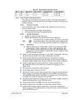
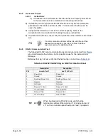
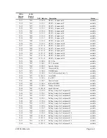
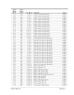
Table 6–5 RS-485 Terminations
Serial Comm Port
1
2
Jumper
J9
J11
First or Intermediate Unit
pins 2–3
pins 2–3
Last or Only Unit
pins 1–2
pins 1–2
6.6.8
RS-485 Communication Test
Before performing this test on the termination panel located inside the rear end
cap, verify that the wiring is correct (see
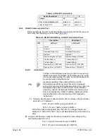
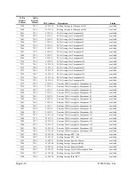
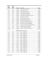
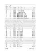
Table 6–6 RS-485 Field Wiring on NGC Termination Panel
Description
Description
PIN
J8–Port 1
J10–Port 2
1
Power
Power
2
Ground
Ground
3
Switched Power Out
Switched Power Out
4
Operate
Operate
5
Remote Request to Send
Remote Request to Send
6
Transmit Bus (+)
Transmit Bus (+)
7
Transmit Bus (-)
Transmit Bus (-)
8
Receive Bus (+) (RS-422)
Receive Bus (+) (RS-422)
9
Receive Bus (-) (RS-422)
Receive Bus (-) (RS-422)
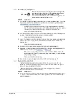
6.6.8.1
Instructions
Voltage on the following steps may be hard to see using a
digital multi-meter. If available, an oscilloscope will provide
a more accurate reading. To verify, the host software must
be continuously polling the meter.
Generally speaking, these tests performed on the
termination panel will only verify incorrect or damaged
wiring. If all previous testing passed and all wiring, jack and
terminations have been verified correct, the termination
panel may need to be replaced. But the termination panel
does not typically fail. Contact Totalflow customer service.
See Getting Help in the introduction of this manual for
instructions.
1)
Using an oscilloscope, measure the line driver voltage on the termination
panel J8 or J10 between:
Port 1, J8–pin 7 (BUS-) and pin 6 (BUS+) or
Port 2, J10–pin 7 (BUS-) and pin 6 (BUS+).
When the unit is receiving data from the host, the voltage should vary
b5 VDC and 0 VDC. This would indicate that the unit is receiving
data.
2)
Using an oscilloscope, measure the remote request to send voltage on the
termination panel J8 or J10:
Port 1, J8–pin 2 (Ground) and pin 5 (RRTS)
Port 2, J10–pin 2 (Ground) and pin 5 (RRTS)
Содержание NGC8206
Страница 1: ...2101510 rev AG NGC8206 Chromatograph User s Manual ...
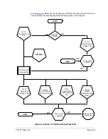
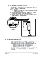
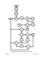
Страница 14: ...xii Figure 6 3 AC Charger Power Supply Wiring 6 28 Figure 6 4 Communication Troubleshooting Flowchart 6 30 ...
Страница 27: ...Page 2 8 2101510 Rev AG Figure 2 4 NGC8206 Enclosure Figure 2 5 NGC8206 Enclosure Left Side ...
Страница 60: ...2101510 Rev AG Page 2 41 hex socket set screw on cap Figure 2 32 Explosion Proof AC Power Supply ...


