


4 November 2005
641P026-008
HMB-8 / HMB-8.7 Mechanism
©
(formerly HMB-11)
Page 10
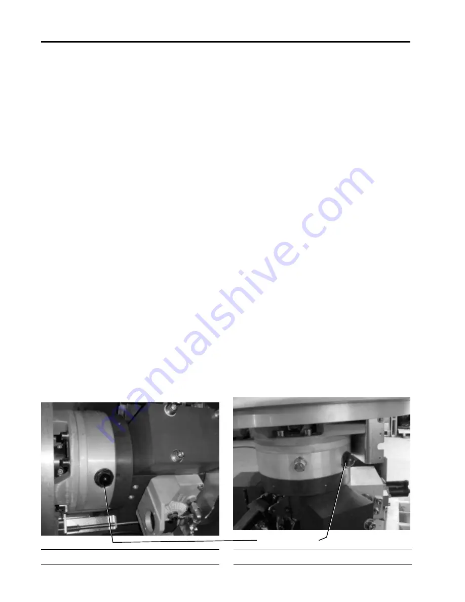
Plate 1: Oil level indicator (Horizontally-oriented)
4.2.4
Limits on Pump Motor Operation
During commissioning and testing, the number of pump
motor operations should be limited to 20 complete charg-
ing operations per hour (from zero spring charge to full
spring charge), or 30 pump starts after close-open opera-
tions, to avoid overheating the motor. During extensive
testing, remove the mechanism cover 51028 (Fig. 1) to help
cool the charging motor. Touch the case of the charging
motor occasionally to be sure that it is not overheating.
Caution
Pump motor operating duty is limited to 20
complete charging operations per hour due to
the thermal capacity of the pump motor.
Important:
When reattaching the mechanism cover
51028, torque the cover bolts to 3 Nm.
4.3
General Maintenance Procedures
General maintenance procedures include:
• Checking the hydraulic oil level (section 4.3.1);
• Draining the hydraulic oil (section 4.3.2);
• Replacing the pump element 51014 (Fig. 5) (includ-
ing check valve 51059) and filter 51079 and (section
4.3.3);
• Replacing the close and open pilot valves 51004
and 51005 (Fig. 8) (section 4.3.4);
• Evacuating the mechanism (section 4.3.5);
• Oil refilling (section 4.3.6);
• Replacing the pump motor (section 4.3.7);
• Leak check the hydraulic system (section 4.3.8);
• Adjusting the pump limit switches (section 4.3.9);
• Checking the pump start counter (section 4.3.10).
4.3.1
Checking the Hydraulic Oil Level
Check the oil level in the oil level indicator 51036 (sight
glass) (Fig. 1 and Plate 1) with the spring assembly fully
compressed and the breaker in the CLOSED or OPEN
position. The oil level should be no less than 1/3 of the
total window for a horizontally-oriented mechanism (Plate
1) or 1/4 of the total window for a vertically-oriented
mechanism (Plate 2). The oil level can be distinguished
by its red color. If the oil level is low, hydraulic oil needs to
be added as described in section 4.3.6.1. The oil level
should not be more than 1/2 of the window. Drain oil if
necessary, using the drain valve.
4.3.2
Draining the Hydraulic Oil
To drain hydraulic oil from the HMB mechanism:
1.
Remove the mechanism cover 51028.
2.
Place the mechanism in the OPEN position and dis-
charge the disc spring assembly 51008 (Fig. 1).
3.
Drain the hydraulic oil into a clean, 5-liter size container
by opening the oil drain valve 51013 and oil fill port
51127. The mechanism contains approximately 2.1
liters of hydraulic oil.
4.
After draining the oil, close the oil drain valve 51013.
5.
Re-install the plug on the oil fill port 51127 to keep out
dirt and debris.
6.
Proceed to sections 4.3.5 and 4.3.6.2 to evacuate and
refill the mechanism with hydraulic oil.
4.3.3
Replacing the Pump Element (including Check
Valve and Filter)
Refer to section 4.3.3.1 to replace the pump element.
4.3.3.1 Replacing the Pump Element
To replace the pump element 51014 (Fig. 5):
1.
Remove the mechanism cover 51028.
2.
Be sure that the mechanism is in the OPEN position
and the pressure inside the mechanism is equalized
as described in section 4.1.1.
3.
Drain the hydraulic oil from the mechanism by per-
forming the procedure described in section 4.3.2.
4.
Remove the pump motor 51002 (Fig. 5).
Oil Level Indicator
Plate 2: Oil Level Indicator (Vertically-orientated)
Содержание Mechanism HMB-8
Страница 2: ......
Страница 5: ...641P026 008 HMB 8 HMB 8 7 Mechanism formerly HMB 11 Page 5 4 November 2005 ...
Страница 19: ...641P026 008 HMB 8 HMB 8 7 Mechanism formerly HMB 11 Page 19 4 November 2005 NOTES ...
Страница 33: ...641P026 008 HMB 8 HMB 8 7 Mechanism formerly HMB 11 Page 33 4 November 2005 NOTES ...