Maintenance
Warning!
The safety functions and the mechanics shall be tested regularly. Check
correct operation of all circuits and the lock function at least once a year.
Caution!
The electromagnet shall be regularly cleaned to maintain its full holding
power. Dirt or dust on the anchor plate or Magne can cause low or no holding power.
Warning!
In case of breakdown or damage to the product, remove and replace it
with a new unit. Contact the nearest ABB Jokab Safety Service Office or reseller. Do
not try to repair the product yourself.
Never
bypass the safety circuit.
Warning!
ABB Jokab Safety will not accept responsibility for failure of the switch
functions if the installation and maintenance requirements are not implemented.
Instructions for
Testing safety function and Replacing Eva Unique code, see Magne 3
and 4 Product Manual.
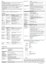
LED indication
Troubleshooting:
Technical data
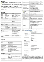
Manufacturer
Address
ABB AB, Jokab Safety
Varlabergsvägen 11
SE-434 39 Kungsbacka
Sweden
Mechanical data
Anchor plate material
Iron with nickel coating
Electromagnet material
Iron with zink-nickel coating
Housing material
Anodized aluminium and polycarbonate
Potting material
PUR, epoxy
Enclosure protection
IP67
Ambient temperature
Operating temperature: -20 °C to +50 °C
Storage temperature: -20 °C to +70 °C
Holding force
Up to 1500 N (on correct installation)
Anchor plate permanent magnet 32B holding force: 30 N
Humidity
35-85 % (without ice formation or condensation)
Weight
Magne 3: 610 g
Magne 4: 700 g
Anchor plate (32A/32B): 290 g
Electrical data
Operating voltage
Electro24 VDC ±15 %
Current consumption
+24 VDC:
Magne 3: 10 mA
Magne 4: 40 mA
Note: Any current drawn on outputs (e.g. the information
output) will be an additional input current on +24 V.
Locking signal:
Typically 250 mA at 24 VDC, max 350 mA at 27.6 VDC
Information output
max 20 mA
Cable dimension
Cable dimensioning should be checked when connecting
several units in series. Standard cables from ABB/Jokab
Safety have a cross sectional area of 0.34 mm
2
. Magne does
not cause any power surge when locking is activated.
Connector
M12 5-pole male connector (Magne 3X, Magne 4X DYN)
M12 8-pole male connector (Magne 4 DYN-Info, Magne 4
DYN-2Info and Magne 4 OSSD-Info)
Standard compliance and approvals
European directives
Machine Directive 2006/42/EC
EMC directive 2014/30/EU
RoHS directive 2011/65/EU
Application standard
compliance
EN ISO 14119:2013, EN 60947-5-3:2013
Functional safety standard
compliance
EN ISO 13849-1:2015, PL e/Category 4,
PFH
D
: 4.50×10
-9
EN 62061:2005 + A2: 2015, SILCL3, PFH
D
: 4,5×10
-9
EN 61508:2010,
SIL3, PFH
D
: 4.50×10
-9
Warning!
The safety related values are based on interlocking device
Eden and are not valid for the locking function
Electrical safety standard
compliance
EN 60204-1:2006 + A1:2009
Electromagnetic
compatibility standard
compliance
EN 61000-6-2:2005,
EN 61000-6-4:2007 + A1:2011,
IEC/EN 60664-1:2007 + A1:2011
Approvals
Certifications
cULus, TÜV Süd
Information for use in USA/Canada (UL)
Enclosure
Type 1
Intended usage
Applications as NFPA 79
Connecting cables
Cables to comply with CYJV/7, with a conductor area of min
0.2 mm
2
.
Power source
The Limited Voltage / Current source must comply with one
of the following:
a) An isolating device such that the maximum open circuit
voltage potential available to the circuit is not more than 24
VDC and the current is limited to a value not exceeding 8
amperes measured after 1 minute of operation.
b) A suitable isolating source in conjunction with a fuse in
accordance with UL248. The fuse shall be rated max. 3 A
and be installed in the 24 VDC power supply to the device
in order to limit the available current.
Conductor area
Max current limit for overload protection:
AWG (mm
2
) Amps
24 (0,20)2
22 (0,32)3
20 (0,52)5
18 (0,82)7
For further details regarding the interlock switch, refer to Eden original instructions
available at
Descriptions and examples show how the product works and can be used. It does not
mean that it fulfills the requirements for all types of machines and processes. The
buyer/user is responsible for installing and using the product according to applicable
standards and regulations. We reserve the right to make changes to the product and
the documentation without prior notice.
2TLC172315M0201
_K
Magne model
LED Indication
Description
Magne 4
Green
Eva within sensing distance, safety
circuit closed
Magne 4
Fast flashing green
Eva within 2 mm of maximum distance
Magne 4
Flashing green-red
Eva within sensing distance, safety
circuit broken before this unit
Magne 4
Red
Eva out of sensing distance, safety
circuit broken
Magne 4
Flashing red
No Eva programmed
Magne 4
Fast flashing red
Fail safe mode
Magne 4 (OSSD)
Fast flashing red-red-green
Invalid
input signal
Magne 3 and 4
Flashing blue
Magne is not detecting the anchor plate
Magne 3 and 4
Blue
Magne is locked
LED Indication
Probable cause
Action
No LED
No voltage
Check +24 VDC power supply.
Flas
h
ing blue
Anchor plate is missing
or not cent
e
red
Check anchor plate position.
Red (solid light)
Eva away from Adam or
metal between Eva and
Adam
Move Eva within sensing distance of
Adam. Remove metal.
Green + red
Unit is defective
Replace the unit. Contact
ABB Jokab Safety.
Fast flashing
green - red
Valid Eva code missing
Replace Eva. If it still does not work, the
unit is defective and must be replaced.
Fast flashing red
Fail safe mode
Power cycle (i.e.turn off power, wait for
1 minute and turn it on again).
Flashing green -
red
Input signal is missing
1. Check output signal from the
previous unit in the signal chain.
2. Turn off power supply.
3. Move Eva within sensing distance.
4. Power supply.
Flashing red –
red – green
OSSD only
Invalid
input signal
Power cycle (i.e. turn off the power,
wait for 1 minute and turn it on again).
If fault recurs, check incoming signals.

