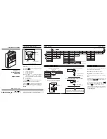


Flow Rng
Flow Unit
5.00000
m^3/Hr
PROGRAMMING
ANALOG OUTPUT
Display Setting
2
3
4
5
6
7
8
9
Seconds
2
3
4
8
15
30
60
120
Caution. Access is NOT possible without the
correct password. 'Lost' passwords can ONLY be
reset by the Service Engineer.
PARAMETER
DESCRIPTION
Alarm No1 Idle
Idle state for alarm output.
With no alarm active:
0 = Low (O/P transistor ON)
1 = High (O/P transistor OFF)
Alm No1 En
0 = Alarm output disabled (set to
idle state).
1 = Alarm output enabled.
Alm No1 Fault
Alarm occurs for System fault.
Alm No1 Fwd
Alarm occurs for forward flow.
Alm No1 Rev
Alarm occurs for reverse flow.
Alm No1 Cutoff
Alarm occurs for Pulse Output
Cutoff.
Alm No1 Mtsnsr
Alarm occurs for empty sensor.
Alm No1 Hi
Alarm occurs for Flow
≥
‘Alm Trip Hi’.
Alm No1 Lo
Alarm occurs for Flow
≤
‘Alm Trip Lo’.
Alm No1 Anlg
Alarm occurs for Analogue Output
over range.
Alm No1 Pls
Alarm occurs for Pulse Output over
range.
PARAMETER
DESCRIPTION
Tot Unit
Select totaliser measurement units.
Tot Mult
Select multiplier units required.
Tot ClrEn
Enter '1' to enable totaliser reset
function to be used from front panel.
PARAMETER
DESCRIPTION
Inpt
Set up external logic input function:
'Zero' sets flowrate output to zero.
'Hld' holds flowmeter output value.
'Clr' resets all totalizers.
'Anlg' selects Anlg No2 Range.
Inpt Idle
Enter inactive state of input contact:
'1' for Hi normal
'0' for Lo normal.
SECURITY PASSWORD
Login Key 1
Set Level 1 security password.
Login Key 2
Set Level 2 security password.
# The maximum which can be entered must not exceed
21000. The value entered may be displayed with a small
error in the decimal digits e.g. 1.900 may be displayed as
1.899. This is a display characteristic and the value 1.900
will be used by the MagMaster.
§ Select both parameters for bidirectional operation (e.g.
when dual current output is fitted). If both are zero, then I
OUT
is always 0%.
‡ On performing a Rapid Reset/Escape to return to
'Operation' level, 'Test Mode' is automatically cancelled.
Ø If the sensor is empty or disconnected, the alarms
'MtSnsr' and 'Coil' will be displayed as appropriate.
PARAMETER CHANGES
FLOW MEASUREMENT
When a parameter is selected, which holds one or more
variable units e.g. 'Flow Unit' parameter which can be
Liters, Cubic meters, Gallons etc., proceed as follows to
change the units: ('Flow Rng' selected).
'Flow Unit' selected
Press
or
switch to change the units.
✶
Note. The existing units will flash at the first
depression of the
or
switch, and further
switch depressions will change the type of units
displayed.
Depressing the
switch will now enter the newly
selected units.
This type of action is similar for all variable units.
Where numerical values are to be changed, initial
depression of the
or
switches cause the first of
five digits to be highlighted by a flashing cursor. Change
the value with the
and
switches, the particular
digit with the
switch, and enter the final selection with
the
switch.
The correct security level MUST be selected – see
SECURITY ACCESS.
Select the parameter to read the value, or to change it as
necessary. All ‘live’ data displayed is updated each
second.
Use the
key to move between pages.
Use the
key to move between parameters.
The
and
keys change displayed values and units.
The
key will accept the chosen value or unit.
PARAMETER
DESCRIPTION
Flow Range
Enter main full scale (100%) flow
range (Upper Range Value) in
selected flow units. #
Flow Unit
Select Units as required.
Ltr (Liters)
m^3 (Cubic Meters)
IGal (Imp Gals)
UGal (U.S. Gals)
ft^3 (Cubic Feet)
Flow Mult
Select multiplier as required.
m (0.001)
c (0.01)
x1 (1)
h (100)
k (1000)
M (1000000)
Flow Time
Select time units as required.
s (Second)
Min (Minute)
Hr (Hour)
Dy (Day)
Wk (Week)
Flow Resp
Nominal Time Constant for output.
Enter Display Setting from table
below for time constant required.
Flow %
Present flow as % of range.
Flow Probe Ins
Probe Insertion Factor.
Flow Probe Prf
Probe Profile Factor
Flow Cutoff
Flow velocity in mm/sec. below
which flow set to 0.
PARAMETER
DESCRIPTION
Anlg Fsd
Enter output current in mA for 100%
flow (0
≤
FSD
≤
21)
Anlg Zero
Enter output current in mA for 0%
flow (0
≤
ZERO
≤
21)
Anlg No2
Full scale flow range for 2nd analog
range, as % of main flow range.
Anlg mA
Present output current (mA)
Anlg Dir Fwd
Output responds to forward
flow if set to '1'. §
Anlg Dir Rev
Output responds to reverse
flow if set to '1'. §
OUTPUT PULSE
PARAMETER
DESCRIPTION
Pls Fact
Enter required output pulses per
flow volume unit.#
Pls Cutoff
Flow rate (%) below which pulse
output and totaliser cease to operate.
Pls Max
Maximum output frequency in Hz.
Pls Hz
Display of present output frequency in
Hz (live value).
Pls Idle
Idle state for Pulse Output with no
output pulse (e.g. at zero flow).
0 = Low (output transistor ON)
1 = High (output transistor OFF)
Pls Size
Enter output pulse width in msecs.
(Value will be rounded up to nearest
10ms). Set to ‘0’ for square wave
output.
ALARMS (CONTD.)
PARAMETER
DESCRIPTION
Alarm No2 Idle
Identical to, but independent of
Alarm No1 above.
Alarm No2 Pls
Alarm occurs for Pulse Output
over range.
TEST MODE
PARAMETER
DESCRIPTION
Disp Res
Enter number of decimal places
required on flow display (0 to 5).
Disp Mode
Serial Communication display
mode (Read Only) – attempts to
edit this parameter result in display
of 'Keypad Version No.' with
eventual return to normal
operation.
DISPLAY RESOLUTION
PARAMETER
DESCRIPTION
Test Mode
Set to '1' to enable.
Test Flow
Displays present flowrate.
If in 'Test Mode', any value may be
entered manually. ‡
Test %
Flowrate as a percentage
Test Hz
Output Frequency
Test mA
Output Current
Test Vel
Flow Velocity in sensor
Test Alm
Shows present active alarms
sequentially. ('Clr' indicates no
alarms are active). Ø
Test Txv
Live flow velocity (uncorrected for
sensor calibration).
SENSOR CALIBRATION
PARAMETER
DESCRIPTION
Snsr No
Serial No. (Up to 13 characters)
Snsr Tag
Tag No. (If required).
Snsr Size
Sensor calibrated bore (mm).
Snsr Vel
Display of present velocity.
Snsr Fact 1
Snsr Fact 2
Sensor calibration data –
Snsr Fact 3
should agree with sensor data label
Snsr Fact 4
PARAMETER
DESCRIPTION
Mtsnsr Trip
Set empty pipe detector trip
threshold.
Mtsnsr mV
Measured value related to fluid
conductivity.
ALARMS
EMPTY PIPE DETECTION
PARAMETER
DESCRIPTION
Alarm trip Hi
High flow alarm trip point as % of
range.
Alarm Trip Lo
Low flow alarm trip point as % of
range.
Alm Trip Hyst
Enter hysteresis for alarms as % of
range.
Alm Trip Disp
Set to ‘1’ if Hi/Lo Alarms are to be
displayed.
INPUT CONTACT
TOTALIZER


