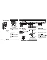


Controls and Display
Upper display gives continual update of flow rate in
selected units.
By pressing the
key, the lower display steps through
the following sequence:
>
Forward flow total value.
<
Reverse flow total value
*
Net flow total value
Alm
Active alarms – Any alarms are displayed
sequentially if more than one alarm is present.
'Alm Clr' is displayed when no alarms are present.
Vel
Flow Velocity
%
% of Flow Range.
Pressing the
key resets the flow total displayed on the
upper display, if parameter 'Tot Clr En' is enabled.
Pressing the
key accesses the Login Parameter
where it is necessary to enter a security code before any
other parameters can be accessed – see SECURITY
ACCESS.
Snsr Fact 1
Snsr Fact 2
Snsr Fact 3
Snsr Fact 4
Inpt
Mtsnsr Trip
Mtsnsr mv
Snsr No
Snsr Tag
Snsr Size
Snsr Vel
Inpt Idle
Test Mode
Test Flow
Test %
Test Hz
Test mA
Test Vel
Test Alm
Test Txv
Disp Res
Login Key 1
Login Key 2
Return to 'Flow Rng' Page
Disp Mode
Alm Trip Hi
Alm Trip Lo
Alm Trip Hyst
Alm Trip Disp
Flow Rng
Flow Unit
Flow Mult
Flow Time
Flow Rspns
Flow %
Flow Probe Ins
Flow Probe Prf
Anlg Fsd
Anlg Zero
Anlg No2
Anlg mA
Anlg Dir Fwd
Anlg Dir Rev
Pls Fact
Pls Cutoff
Pls Max
Pls Hz
Pls Idle
Pls Size
Alm No1 Idle
Alm No1 En
Alm No1 Fault
Alm No1 Fwd
Alm No1 Rev
Alm No1 Cutoff
Alm No1 Mtsnsr
Alm No1 Hi
Alm No1 Lo
Alm No1 Anlg
Alm No1 Pls
Tot Unit
Tot Mult
Tot ClrEn
Alm No2 Idle
Alm No2 En
Alm No2 Fault
Alm No2 Fwd
Alm No2 Rev
Alm No2 Cutoff
Alm No2 Mtsnsr
Alm No2 Hi
Alm No2 Lo
Alm No2 Anlg
Alm No2 Pls
Press moves
Flow Cutoff
Key
Security Level 1
Security Level 2
Press
moves
CONTROLS AND DISPLAY
MENU LAYOUT
…MENU LAYOUT
Two security code levels, 1 and 2, are available, and are
each accessed with a five digit number.
User Code Level 1 default number is 10760.
Engineer Code Level 2 default number is 56360.
Parameters accessible by the two levels are shown
above.
At the flashing cursor on the first digit of the Login code
number, press either
or
membrane switches to
reach the required digit.
To set this digit and pass to the next digit, depress the
switch. Continue until all digits have been set, and
depress the
switch to enter the complete code.
If an incorrect value is entered, access to subsequent
programming pages is prevented and the display reverts
to the Operating Page.
Quick Reference Guide
Kent -T
aylor
MagMaster
ASEA
BROWN BOVERI
MagMaster
TM
Electromagnetic
Flowmeters
Keypad Version
A – Advancing to Next Page
Parameter 1
Parameter 2
Parameter 3
Parameter 4
Page 1
Parameter 1
Page 2
Advance to
next page
or
B – Moving Between Parameters
Parameter 1
Parameter 2
Parameter 3
Parameter 4
Advance to
next parameter
Parameter 5
Parameter 6
Parameter 2
Membrane
Switches
Resets totaliser, if parameter
'Tot Clr En' is enabled
Upper
Display
Lower
Display
MagMaster
Kent-Taylor
32.8
Ltr/s
>42315
SECURITY ACCESS
IM/MM-QRG Iss 1 5/96
CONTROLS AND DISPLAY
Depressing this switch for 5 seconds and then releasing
it will exit the menu system and return to normal operating
mode.
ASEA BROWN BOVERI
ABB Kent-Taylor
Oldends Lane, Stonehouse, Gloucestershire, England GL10 3TA
Telephone: 01453 826661, Facsimile: 01453 826358
C – Adjusting and Storing a Parameter Value
New value is
automatically stored
Parameter Value
or unit
Adjust
D – Selecting and Storing a Parameter Choice
Parameter X
Y
Z
Select
New value is
automatically stored
Advance to next digit


