ABB KP-800 Скачать руководство пользователя страница 8

11

12

13

Install Emax 2 Breaker

Install the moving part of the circuit breaker into the fixed part per instructions in the Emax 2 installation, 
operation and maintenance manual 1SDH001000R0002.

Comply with the instructions in that manual for commissioning the new circuit breaker .

Refer to the section in the manual for the circuit breaker requirements for clearances within the compartment.

Optional Auxiliary (Secondary) Circuits Notes:

The installed auxiliary circuits have been wired in accordance with the supplied wiring diagrams which are 
based on customer furnished information.  Review the wiring diagrams for integration and compliance to the 
switchgear circuitry.

Prior to energizing the auxiliary circuits, verify that the secondary contacts are properly engaged by performing 
a continuity test on each installed circuit.

Review the “Putting into service” section of the Emax 2 installation, operation, and maintenance manual 
1SDH001000R0002 for specific checks of the installed accessories.

Fan operation on CiC adapters which include forced cooling (as noted in Table A on page 1) should be verified 
during the installation accessory checks and during second level maintenance schedule operations.

MAKING THE SYSTEM SAFE FOR REMOVAL

The following warnings and precautions must be respected before removing the circuit breaker and CiC from the 
switchgear.

The trained personnel in charge of handling and lifting must use appropriate safety equipment.

Place the switchgear housing and the circuit breaker out of service.

Disconnect the power from the switchgear (power circuit and auxiliary circuits) and verify it is disconnected 
from all sources of energy.

Set the circuit breaker to the open position with the springs unloaded.

Double-check to ensure that the line has been placed out of service.

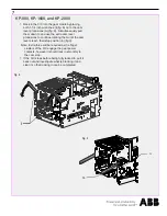
Removal is done in the reverse order of the 
installation steps in sections 6, 5, 4, 3, and 2.  The 
CiC should rack out smoothly without mechanical 
interference.

Note:  If any unusual resistance is detected that 
could be abnormal interference between the CiC 
and compartment parts, stop immediately and 
examine what is causing the interference and 
correct the situation.

Remove the Emax 2 Cradle in Cradle

Содержание KP-800

Страница 1: ... plug in features as established in the operation and maintenance manual of the new Emax 2 circuit breaker without having to modify any of the live parts of the switchgear ATTENTION The instructions concern the sole assembly of the retrofitting kit They do not substitute for the instruction in the installation operation and maintenance manual of the Emax 2 circuit breaker installation instructions...

Страница 2: ...pment Remove the obsolete OEM circuit breaker Open the door of the switchgear Refer to the OEM installation manual for instructions to remove the breaker from service WARNING THE CIRCUIT BREAKER COULD DROP DURING THIS OPERATION BEFORE PROCEEDING REFER TO THE OEM MANUAL FOR LIFTING AND REMOVAL INSTRUCTIONS AND USE APPROPRIATELY SIZED AND RATED LIFTING DEVICE BEFORE PROCEEDING Optional Disconnect an...

Страница 3: ...f the CiC Rotate the cam lever g on both sides into the position as shown The CiC cannot be installed in the gear with the Emax 2 breaker installed Unscrew the breaker lock out pin d fig 3 on both sides where shown until it stops and the cam levers are free to rotate Do not force them past the stop or remove them Fig 3 Fig 4 Fig 5 d WARNING THE CiC COULD DROP DURING THIS OPERATION BEFORE PROCEEDING...

Страница 4: ...ing lever h fig 6 drops down Fig 6 Press down on the rail levers on the KP 800 KP 1600 and KP 2000 b fig 7 on both sides to release the rails Slide the CiC and rails into the gear cradle until the cam lever spindle j stops in the gear cradle racking slot guide k Fig 7 k b j ...

Страница 5: ...inue rotating them until the cam levers reach their stop position n fig 9 Note Extra force will be required as the finger clusters of the CiC engage the gear power contacts however it should rack in smoothly to the cam stop If the CiC stops before being fully racked in pull it back out and investigate what is blocking it and clear it so that racking in can be completed Fig 9 n m KP 800 KP 1600 and K...

Страница 6: ...0 11 on both sides where shown until it stops Do not force them past the stop or remove them Lock out pins should protrude into the path of the cam levers and prevent them from being rotated when the breaker is installed in its cradle Fig 10 d KP 800 KP 1600 and KP 2000 fig 11 d Fig 15 Fig 12 If a flange for the old circuit breaker exists on the door disassemble and dispose it fig 12 ...

Страница 7: ...r along the unbroken line and drill holes in the positions marked by the holes fig 14 Mount the dust guard escutcheon s fig 15 provided with the breaker to the door 1B Fig 15 Cut lines 14x 0 2 in 5 mm Ø Fig 14 s KP 800 KP 1600 and KP 2000 13 28 lb in 1 5 Nm NOTE If the dotted line on the adhesive template fails to perfectly match the existing opening in the door refer to the instructions for insta...

Страница 8: ...an operation on CiC adapters which include forced cooling as noted in Table A on page 1 should be verified during the installation accessory checks and during second level maintenance schedule operations MAKING THE SYSTEM SAFE FOR REMOVAL The following warnings and precautions must be respected before removing the circuit breaker and CiC from the switchgear The trained personnel in charge of handl...

Страница 9: ... 2020 ABB All rights reserved www abb com For more information please contact your local ABB Field Representative or Service Center listed below ABB Inc 1555 Scott Street Senatobia MS 38668 Phone 1 662 562 0700 ...

Отзывы: