background image

2 DressPack and SpotPack

2.7.1 Introduction

100

Rev.E

3HAC 025861-001

Split box/Connection box

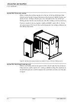
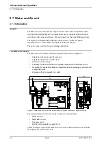
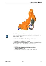
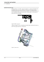
With the split box, the 24VDC supply and signals are connected and distributed to 

the different units on the water and air unit, see Figure 65. The design makes 

disconnection of separate items for service and repair on the water and air unit very 

easy. The split box has a protection class IP67, which means it is well protected 

against dust and water leakage.

Figure 65  Split box connections.

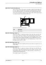
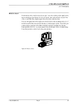
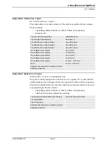
Cables for option 781-2 are routed directly from the Water And Air unit to the con-

nection box at the robot base, see Figure 66.

Figure 66  Connection box.

Содержание IRB 6620

Страница 1: ...Product specification Articulated robot IRB 6620 150 2 2 M2004...

Страница 2: ......

Страница 3: ...Product specification Articulated robot 3HAC025861 001 Rev E IRB 6620 150 2 2 M2004...

Страница 4: ...ess for a specific purpose or the like In no event shall ABB be liable for incidental or consequential damages arising from use of this manual and products described herein This manual and parts there...

Страница 5: ...ment 28 1 5 4 Wrist torque 29 1 6 Mounting of equipment 30 1 6 1 General 30 1 7 Maintenance and Troubleshooting 34 1 7 1 Introduction 34 1 8 Robot Motion 35 1 8 1 Introduction 35 1 8 2 Performance acc...

Страница 6: ...inet 94 2 7 Water and Air unit 96 2 7 1 Introduction 96 2 7 2 Technical data Water and Air unit 104 2 8 Tip Dresser 105 2 8 1 Introduction 105 2 9 Connection kits 109 2 9 1 Options 109 3 Specification...

Страница 7: ...and Product personnel Sales and Marketing personnel Order and Customer Service personnel Contents Please see Table of Contents on page 3 Revisions Revision Description Revision New product specificat...

Страница 8: ...ication Description Controller IRC5 with FlexPendant 3HAC021785 001 Controller Software IRC5 RobotWare 5 11 3HAC022349 001 Robot User Documen tation IRC5 and M2004 3HAC024534 001 Product Manual Descri...

Страница 9: ...e Safety to protect not only personnel in the unlikely event of an acci dent but also robot tools peripheral equipment and the robot itself Operating system The robot is equipped with the operating sy...

Страница 10: ...ted on to the floor or inverted a tilting of 15 is allowed for both mountings Manipulator weight Other technical data Robot Type Handling capacity kg Reach m IRB 6620 150 kg 2 2 m Robot type Weight IR...

Страница 11: ...nipulator from the front side rear and above dimensions in mm Allow 200 mm behind the manipulator for DressPack Type of Movement IRB 6620 ISO Cube 2 8 kW Pos Description A R 199 mm for wrist rotation...

Страница 12: ...ustrial environments Safety requirements EN 61000 6 4 option EMC Generic emission EN 61000 6 2 EMC Generic immunity Standard Description IEC 60529 Degrees of protection provided by enclosures Standard...

Страница 13: ...tion brakes released is indicated on the FlexPendant Data can also be monitored over network using e g WebWare The Active Safety System Description General The active safety system includes those soft...

Страница 14: ...itored by two independent computers Restricting the working space The movement of each axis can be restricted using software limits Axes 1 and 3 can also be restricted by means of mechanical stops Col...

Страница 15: ...e FlexPendant must be used to move the robot when in manual mode The enabling device consists of a switch with three positions meaning that all robot movements stop when either the enabling device is...

Страница 16: ...d on the robot tool flange axis 6 See Load diagram 1 5 2 Diagrams Extra loads An extra load of 50 kg for instance DressPack can be mounted on to the upper arm An extra load of 100 kg can be mounted on...

Страница 17: ...nipulator during operation Standard 5 C 41 F to 50 C 122 F For the controller Standard Option See Product specification Controller IRC5 with FlexPendant For the spot welding cabinet Standard 5 C 41 F...

Страница 18: ...tem Figure 3 Directions of forces Note regarding Mxy and Fxy The bending torque Mxy can occur in any direction in the XY plane of the base coordinate system The same applies to the transverse force Fx...

Страница 19: ...re 4 Hole configuration dimensions in mm Recommended screws for fastening the manipulator to the base M24 x 100 8 8 with 4 mm flat washer Torque value 775 Nm Only two guiding sleeves shall be used The...

Страница 20: ...1 Regarding AbsAcc performance the chosen guide holes according to Figure 4 and Figure 8 are recommended Base plate drawing Figure 5 Base plate dimension print main dimensions and holes measurements d...

Страница 21: ...1 Description 1 3 3 Mounting the manipulator 3HAC 025861 001 Rev E 19 Figure 6 Base plate dimension print measurements of the adaption for the robot base dimension in mm...

Страница 22: ...Rev E 3HAC 025861 001 Two guiding sleeves required dimensions see Figure 7 Figure 7 Sections of base plate and guide sleeve dimensions in mm Figure 8 Sections of base plate dimensions in mm Pos Descr...

Страница 23: ...the Calibration Pendulum please see Operating manual Calibration Pendulum Figure 9 All axes in zero position Calibration Calibration Position Calibration of all axes All axes are in zero position Cali...

Страница 24: ...ccuracy calibration is focusing on positioning accuracy in the cartesian coordinate system for the robot It also includes load compensation for deflection caused by the tool and equipment Tool data fr...

Страница 25: ...ent or calculation Absolute Accuracy is a RobotWare option and includes an individual calibration of the robot mechanical arm Absolute Accuracy is a TCP calibration in order to Reach m a good position...

Страница 26: ...position when integrated in a production cell Figure 11 Seven holes A on a radius of x mm from axis 6 center on the standard tool flange Figure 12 Seven holes B on a radius of x mm from axis 6 center...

Страница 27: ...upper arm housing At different arm load payload and moment of inertia the load diagram will be changed Control of load case by RobotLoad For an easy check of a specific load case use the calculation...

Страница 28: ...1 Description 1 5 2 Diagrams 26 Rev E 3HAC 025861 001 1 5 2 Diagrams IRB 6620 150 2 2 Figure 14 Maximum permitted load mounted on to the robot tool flange at different positions center of gravity...

Страница 29: ...ure 15 Maximum permitted load mounted on the robot tool flange at different positions center of gravity at Vertical Wrist 10o J0 15 kgm2 For wrist down 0o deviation from the vertical line Without extr...

Страница 30: ...16 Moment of inertia when full movement of axis 5 Total load given as Mass in kg center of gravity Z and L in meter and moment of inertia Jox Joy Joz in kgm2 L X2 Y2 see Figure 16 Axis Robot Type Maxi...

Страница 31: ...ption Jox Joy Joz Max moment of inertia around the X Y and Z axes at center of gravity Note The values are for reference only and should not be used for calculating permitted load offset position of c...

Страница 32: ...f distances and mass are shown in Figure 18 The robot is supplied with holes for mounting extra equipment see Figure 19 and Figure 20 Upper arm Permitted extra load on to the upper arm 50 kg The max d...

Страница 33: ...1 Description 1 6 1 General 3HAC 025861 001 Rev E 31 Frame Permitted extra load on the frame is 100 kg Holes for mounting extra equipment Figure 19 Holes for mounting extra equipment...

Страница 34: ...1 Description 1 6 1 General 32 Rev E 3HAC 025861 001 Figure 20 Holes for mounting of extra equipment...

Страница 35: ...SS EN ISO 9409 1 2004 dimensions in mm For fastening of Gripper tool flange to Robot tool flange every other one of the bolt holes for 6 bolts quality class 12 9 shall be used see Figure 21 Pos Descri...

Страница 36: ...as possible Maintenance free AC motors are used Oil is used for the gear boxes The cabling is routed for longevity and in the unlikely event of a failure its modular design makes it easy to change Ma...

Страница 37: ...140 to 65 3 Arm motion 70 to 180 4 Wrist motion 300 to 300 5 Bend motion 130 to 130 Limitations with DressPack 6 Turn motion 300 to 300 default Max 96 Revolutionsa a The default working range for axis...

Страница 38: ...e DressPack holder at Axis 6 there are the following limitations for Axis 5 movement when DressPack Upper arm is used See Figure 22 Figure 22 Limitations for Axis 5 when using DressPack holder Pos Des...

Страница 39: ...tion 1 8 1 Introduction 3HAC 025861 001 Rev E 37 Figure 23 The extreme positions of the robot arm specified at the wrist center dimensions in mm Robot Type Handling capacity kg Reach m IRB 6620 150 2...

Страница 40: ...Programmed path B Mean position at program execution D Actual path at program execution AP Mean distance from programmed position AT Max deviation from E RP Tolerance of posiotion B at repeated positi...

Страница 41: ...1 and at mains power supply failure at max speed max streched out and max load categories according to EN 60204 1 All results are from tests on one moving axis All stop distances are valid for floor...

Страница 42: ...ry Gun Robot Gun Robot Gun and Track Motion Track motion The specific parts related to the servo motor control for electrical welding guns and for track motion configurations are shown in the conceptu...

Страница 43: ...t specification 785 5 Stationary gun This option includes Cable G 7 m length for resolver signals from robot base FB7 to stationary gun axis 7 770 4 First additional drive Drive unit for 7th axis with...

Страница 44: ...n Product specification 785 1 Robot gun This option includes Cables within manipulator for servo power signals servo gun axis 7 770 4 First additional drive Drive unit for 7th axis with corresponding...

Страница 45: ...RB 6620 Track motion deliv ery includes Serial measurement box SMB2 Split box for distribution of servo power to axis 7 and 8 The box is placed on the track motion Cables from serial measurement box t...

Страница 46: ...h option see corresponding Product specification General The robot can be combined with a Track Motion for further details see Product specification IRBT 6004 IRBT 7004 Option Description Product spec...

Страница 47: ...for upper and lower arm contains process cable packages including signals process media water and or air and power feeding for Spot Welding power for customer use Necessary supports and brackets are a...

Страница 48: ...Rev E 3HAC 025861 001 Figure 29 DressPack Spotpack Pos Description A SpotPack Spot Welding cabinet B Robot controller including 7th axis drive for servo gun C DressPack Floor D DressPack Routing base...

Страница 49: ...onized with the robot As there is a big span between different user s need of flexibility depending of the complexity of the operation wrist movements there are three major levels of dress pack soluti...

Страница 50: ...ater and Air unit if such is mounted 2 1 4 Impact on dress pack lifetime There are some robot movements positions that shall be avoided in the robot produc tion program This will improve the lifetime...

Страница 51: ...common information Chapter Option Description 2 3 Type H DressPack for Material Handling Chapter Option Description 2 4 Type Se SpotPack for electrical servo driven transformer guns carried by the rob...

Страница 52: ...terial Handling The table below shows the different DressPack configurations available for Material Handling Figure 31 Available options for Material handling Available DressPack configurations for Sp...

Страница 53: ...is designed to fit to the upper arm routing Figure 33 DressPack Lower arm right side view Material Handling option 778 1 and option 798 1 DressPack Upper arm There is one alternative for the Material...

Страница 54: ...one without connection point between lower and upper arm and one with connection point only for signals see Figure 35 and Figure 36 Figure 35 External with retract arm option 778 2 and option 781 1 F...

Страница 55: ...replaced if damaged One version for all IRB 6640 versions Adjustment for optimal hose cable lengths Spot welding option 781 2 Adjustable bracket axis 6 with position marking Protection hose can easily...

Страница 56: ...A B if applicable and one F Proc 1 Spot welding option 781 1 see Figure 37 Included are A B if applicable C and F Proc 1 4 Spot welding option 781 2 see Figure 38 Included are A B if applicable C and...

Страница 57: ...parts are described in the list below for corresponding parts of the tool see chapter 2 9 Connection kits Pos Description A R1 CP CS B R1 SP Spot Welding Servo gun C R1 PROC 1 Material Handling Spot...

Страница 58: ...d weld power cable end with free end Servo power and feed back cables option end with free end The customer signal cable end with a connector the main parts are described in the list below for corresp...

Страница 59: ...with a Harting connector The different main parts within the connector are described in the list below both with name and Harting article number for corresponding parts of the tool see chap ter 2 9 Co...

Страница 60: ...potPack 2 2 3 Interface description for DressPack 58 Rev E 3HAC 025861 001 Dimensions Dimensions are shown in Figure 42 to Figure 43 Figure 42 External routing Material Handling option 798 1 and 780 3...

Страница 61: ...2 DressPack and SpotPack 2 2 3 Interface description for DressPack 3HAC 025861 001 Rev E 59 Figure 43 External with retract arm option 781 1 Dimensions in mm...

Страница 62: ...essPack and SpotPack 2 2 3 Interface description for DressPack 60 Rev E 3HAC 025861 001 Figure 44 External 781 2 Figure showing IRB 6640 Dimensions in mm Pos Description A Holder arm house B Holder ax...

Страница 63: ...ariant Type H is designed for Material Handling MH application Included modules are shown in Figure 45 Figure 45 Dresspack Routing base to Axis 6 Pos Name A Robot Cabinet IRC5 B DressPack Floor Connec...

Страница 64: ...es and connections inside the I O section for the DressPack are chosen The length and con figuration of the floor harness is specified under the options below Option 94 1 2 3 4 for parallel communicat...

Страница 65: ...1 Introduction 3HAC 025861 001 Rev E 63 The available alternatives and allowed combinations are shown in the schematic Figure 46 below Figure 46 Schematic picture for configuration of DressPack for M...

Страница 66: ...communication Option 778 1 Material Handling Option 798 1 Internal routing DressPack Lower arm One of the options Option 780 3 and Option 798 1 External routing The table below shows the available ty...

Страница 67: ...tility Power Protective earth 2 2 2 2 1 0 5 mm2 0 5 mm2 250 VAC 5 A rms 250 VAC Customer Signals CS Signals twisted pair Signals twisted pair and separate shielded 20 8 20 10x2 8 4x2 0 23 mm2 0 23 mm2...

Страница 68: ...Customer Power CP Utility Power Protective earth 2 2 2 2 1 0 5 mm2 0 5 mm2 250 VAC 5 A rms 250 VAC Customer signals CS Signals twisted pair Signals twisted pair and separate shielded 22 8 22 11x2 8 4...

Страница 69: ...un Included modules are shown in Figure 47 Available configurations with linked option numbers are described below Figure 47 Type Se with Routing base to Axis 6 Available configurations and allowed co...

Страница 70: ...e I O section for the DressPack are chosen The length and configuration of the floor harness is specified under the options below Option 94 1 2 3 4 for parallel communication Option 90 2 3 4 5 for par...

Страница 71: ...4 1 Introduction 3HAC 025861 001 Rev E 69 The available alternatives and allowed combinations are shown in the schematic Figure 48 below Figure 48 Schematic picture for configuration of DressPack for...

Страница 72: ...th a For option 781 2 2 signals 2 2 2 2 1 0 5 mm2 0 5 mm2 250 VAC 5 A rms 250 VAC Customer Signals CS Signals twisted pair b Signals twisted pair and separate shielded c b For option 781 2 18 signals...

Страница 73: ...rms 50 V DC 1 A rms Customer bus CBus Bus signals Bus signals Signals twisted pair At bus board At bus board 6 2 2 6 3x2 0 14 mm2 0 23 mm2 0 14 mm2 Can DeviceNet spec 50 V DC 1 A rms 50 V DC 1 A rms...

Страница 74: ...23 mm2 0 23 mm2 50 V DC 1 A rms 50 V DC 1 A rms Customer bus CBus Bus signals Signals twisted pair At bus board 6 2 6 3x2 0 14 mm2 0 14 mm2 Profibus 12 Mbit s spec 50 V DC 1 A rms Servo motor signals...

Страница 75: ...pot welding function package SpotPack IRB 6620 to run with a servo controlled gun some additional additional to those described in previous section Required general options servo drive options are req...

Страница 76: ...inet equipped with a weld timer from Bosch with an integrated AC thyristor with basic capacity Type Bosch PST 6100 630L1 782 2 Bosch Compact AC This option gives a basic Spot Welding cabinet equipped...

Страница 77: ...tion Type Description 792 1 Water and Air unit type S e Offers the basic water and air unit for type S and Se including splitbox for signal distribution 797 1 Cable to split box 7 m Offers floor cable...

Страница 78: ...tool electrical gun Included main modules are shown in Figure 51 below Available configurations with linked option numbers are described below starting with the DressPack Figure 51 Type HSe with Routi...

Страница 79: ...s and connections inside the I O section for the DressPack are chosen The length and configuration of the floor harness is specified under the options below Option 94 1 2 3 4 for parallel communicatio...

Страница 80: ...1 Introduction 78 Rev E 3HAC 025861 001 The available alternatives and allowed combinations are shown in the schematic Figure 52 below Figure 52 Schematic picture for configuration of DressPack for M...

Страница 81: ...low Parallel communication The table below shows the available type of wires media Type At terminals in cabinet At Connection point Base axis 6 Cable part area Allowed capacity Customer Power CP Utili...

Страница 82: ...Utility Power Protective earth 2 2 2 2 1 0 5 mm2 0 5 mm2 250 VAC 5 A rms 250 VAC Customer Signals CS Signals twisted pair Signals twisted pair and separate shielded 20 8 20 10x2 8 4x2 0 23 mm2 0 23 mm...

Страница 83: ...apacity Customer Power CP Utility Power Protective earth 2 2 2 2 1 0 5 mm2 0 5 mm2 250 VAC 5 A rms 250 VAC Customer Signals CS Signals twisted pair Signals twisted pair and separate shielded 22 8 22 1...

Страница 84: ...85 5 Stationary gun Option 786 1 2 3 4 Connection to first drive cable length to be stated Option 635 3 Spot Servo Software option for servo controlled guns Software option option 635 5 could also be...

Страница 85: ...he circuit breaker for the weld power 790 1 Contactor for weld power Offers a weld contactor with necessary wiring placed inside the Spot Welding cabinet 791 1 Weld power cable 7 m Offers floor cable...

Страница 86: ...power cable Option 786 1 2 3 or 4 Cable goes from robot control cabinet to stationary gun and ends with a 23 pin Souriau connector Type UT 061823SH Resolver signal cable 7 m length included in option...

Страница 87: ...ing splitbox for signal distribution 797 1 Cable to split box 7 m Offers floor cable of 7 m length for signals between the Spot Welding cabinet and to the split box placed on the water and air unit 79...

Страница 88: ...cables between the robot control cabinet and the Spot Welding cabinet cable length 1 5 m connected at rear of the control cabinet and at front of Spot Welding cabinet These cables includes power feedi...

Страница 89: ...2 DressPack and SpotPack 2 6 1 Introduction 3HAC 025861 001 Rev E 87 Figure 56 Exploded view drawing of the Spot Welding cabinet...

Страница 90: ...troduction 88 Rev E 3HAC 025861 001 Figure 57 Different views of the Spot Welding cabinet dimensions in mm The electrical circuits of the Spot Welding cabinet consist of weld power circuit and control...

Страница 91: ...or inverter controls the welding current The welding timer includes control program that gives possibil ity to program different weld sequences The programming is normally done on a programming devic...

Страница 92: ...asic capacity General technical data Description Weld timer and thyristor Bosch PST 6100 630L1 Power feeding 400 600 V AC Max welding current 130 A rms 100 kVA transformer Max wire range incoming powe...

Страница 93: ...service outlet 230 V option 736 1 Mainly for the North American market Option 828 2 Region E Offers 230 V power supply Can neither be combined with service outlet 120 V option 736 2 General technical...

Страница 94: ...system is powered up The fan is required to be used together with Bosch MFDC option 782 7 For the AC options option 782 1 and 2 the need will depend on the welding conditions and surrounding temperatu...

Страница 95: ...ble is connected at terminals to the weld timer Bosch or the contactor when option 790 1 is chosen The cable enters the Spot Welding cabinet via cable gland The other end is equipped with an MC connec...

Страница 96: ...e Option 809 2 3 and 4 Process cable to stationary gun Offers floor cable of 15 22 or 30 m length for process signals between the Spot Welding cabinet and to the stationary gun See option 809 1 for fu...

Страница 97: ...nit XS 103 a a For option 782 2 Bosch Compact are signals for controlling the Water and Air unit included in the dress pack floor cabling and go via cable glands into terminals 1 Modular Harting conne...

Страница 98: ...ater and Air unit has the following main features See Figure 61 Adjustable high speed water flow sensors Adjustable digital pressure switch for air Air filter with auto draining Possibility to balance...

Страница 99: ...ntrolled by a digital signal from the robot control system The circuit begins from left to right with a lead in hole in the mounting plate a G thread is used for the connection of the factory water su...

Страница 100: ...it set to 8 liters per minute at 0 2 MPa water pressure The water return circuit begins from right with a Parker Pushlock adapter suitable for a Parker Pushlock DIN 20 078 A we recommend a Parker Push...

Страница 101: ...f 5 m with a metal protection of the bowl a digital pressure switch and a cross interface containing plugged air outlet ports internal G 3 8 thread There is a digital pressure switch to monitor the ai...

Страница 102: ...unit see Figure 65 The design makes disconnection of separate items for service and repair on the water and air unit very easy The split box has a protection class IP67 which means it is well protecte...

Страница 103: ...o the robot base Figure 67 Water and air unit mounted on the base Type HS robot handles part against a pedestal mounted spot welding gun the Water and Air panel is delivered in a together with the rob...

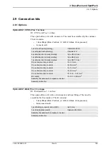
Страница 104: ...ins are available The number in use depends on option choices But at least two are free connection and can be used for customer purposes The Split box has six connections prepared for the following un...

Страница 105: ...e to be arranged by the customer 792 6 Water and Air unit type Sb The basic water and air unit for type S is equipped for a robot handled gun and with the following components Water in circuit Water r...

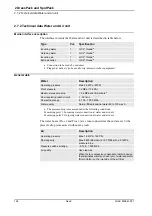
Страница 106: ...Water Description Operating pressure Max 0 6 MPa 87PSI Proof pressure 1 2 MPa 174 PSI Maximum pressure drop 0 2 MPa at 8 litre minutea a The pressure drop is measured under the following conditions Me...

Страница 107: ...Dresser unit The ABB Tip Dresser which is integrated to the robot consists of the following modules see Figure 70 Figure 70 The robot integrated Tip Dresser Pos Name Description A Adjustable stand Ve...

Страница 108: ...izontal tube at the Adjustable stand pos A See Figure 71 The complete Tip Dresser pos A B C and D is mounted with 2 x M20 x 40 120 Nm on to one of the four bolt ears on the robot base See Figure 72 Fi...

Страница 109: ...e To connect the tip dresser to the controller must option 873 1 2 Connection to Tip Dresser be chosen and following parts in the controller are supplied switches contactor signal and power supply cab...

Страница 110: ...to the robot All other necessary components are included in the Spot Welding cabinet Flexible mounting Adjustment of the Tip dresser unit in four directions X Y Z and rotation round the X axis Highes...

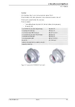
Страница 111: ...Pushlock M22x1 5 Brass 24 degree seal Weld connector with 1 pcs Hood Foundry Harting HAN EMC M 40 1 pcs Hinged frame Harting Shell size 16 2 pcs Multicontact female Harting Type HD 25 pin 1 pcs Multi...

Страница 112: ...7 R3 FB 7 on base This option offers a kit with a connector This must be assembled by the customer The kit contains Connector with 1 pcs Multiple connector pin Souriau 1 pcs Adaptor 8 pin 15 pcs Pin f...

Страница 113: ...t to required length The kit contains 3 Hose fittings Parker Pushlock M22x1 5 Brass 24 degree seal 1 Multi contact connector Female type including 1 pcs Hood Foundry Harting HAN EMC M 40 1 pcs Hinged...

Страница 114: ...Connector with Figure 73 Connector for CP CS CBUS Proc 1 axis 6 1 pcs Housing Harting HAN 1 pcs Hinged frame Harting Shell size 10 1 pcs Multicontact male Harting Type HD 25 pin 1 pcs Multicontact ma...

Страница 115: ...ting Parker Push lock 1 2 M22x1 5 Brass 24 degree seal Connector with Figure 74 Connector for CP CS CBUS Proc1 axis 6 1 pcs UTOW Pin connector 32p Souriau Shell size 18 1 pcs Backshell Souriau Shell s...

Страница 116: ...2 DressPack and SpotPack 2 9 1 Options 114 Rev E 3HAC 025861 001...

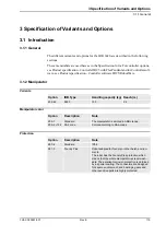
Страница 117: ...5 RobotWare 3 1 2 Manipulator Variants Manipulator color Protection Option IRB Type Handling capacity kg Reach m 435 64 6620 150 2 2 Option Description Note 209 1 Standard The manipulator is painted i...

Страница 118: ...g device on the manipulator for fork lift handling Note When Cooling Fan for axis 1 motor unit is used this must be disassembled in order to use fork lift device 37 1 Base plate Can also be used for I...

Страница 119: ...117 Synchronize labels for Axis 2 Figure 76 Position for synchronize labels Axis 2 Synchronize labels for Axis 3 Figure 77 Position for synchronize labels Axis 3 and Axis 3 with mechanical stop pin S...

Страница 120: ...3 1 3 Equipment 118 Rev E 3HAC 025861 001 Synchronize labels for Axis 5 and 6 Figure 79 Position for synchronize labels Axis 5 and 6 Base connector protection Figure 80 Base connector protection Pos...

Страница 121: ...3 Equipment 3HAC 025861 001 Rev E 119 Manipulator cable protection Figure 81 Manipulator cable protection Insulated tool flange Figure 82 Insulated tool flange dimensions in mm Pos Description A Manip...

Страница 122: ...ol flange according to Euro pean Standard EN 60204 1 withstands dangerous volt age in case of an electrical fault in the spot welding equipment mounted on the Insulated tool flange of 500V DC during 3...

Страница 123: ...imit Axis 1 Option Type Description 29 1 Axis 1 15 degrees Two stops which allow the working range to be restricted in increments of 15 29 2 Axis 1 7 5 degrees Two stops which allow the working range...

Страница 124: ...438 4 Standard 18 months 18 18 months 3 years 438 5 Standard 24 months 18 24 months 3 1 2 years 438 6 Standard 6 months 18 6 months 2 years 438 7 Standard 30 month Warranty extension 30 months 438 8...

Страница 125: ...m Option Connection to Description 16 1 Cabinet The signals CP CS are connected to 12 pole screw ter minals Phoenix MSTB 2 5 12 ST 5 08 in the controller The cable between R1 CP CS and the controller...

Страница 126: ...m 94 3 90 4 22 m 94 4 90 5 30 m 94 7 7 m Only avaialble together with option 781 2 94 8 15 m Only avaialble together with option 781 2 Option Description Note 778 1 Material Handling Includes signals...

Страница 127: ...ervo Gun Option Type Description 459 1 R1 CP CS and PROC1 For the Customer Power Customer Signal connector and one Process connector on the manipulator base Sockets for bus communication are included...

Страница 128: ...he cable length for the Process Cable to the Station ary Gun from the Spot Welding process cabinet to the Stationary Gun Cable to Split Box Following information specifies the cable length for the cab...

Страница 129: ...d to the robot Figure 85 Tip Dresser unit Connection to Tip Dresser The following information specifies the cable length to the Tip Dresser from the Spot Welding process cabinet to the Tip Dresser uni...

Страница 130: ...air cooling See Chapter 2 6 Spot Welding cabinet 789 1 Earth fault protection unit See Chapter 2 6 Spot Welding cabinet 790 1 Contactor for weld power See Chapter 2 6 Spot Welding cabinet Option Type...

Страница 131: ...of Variants and Options 3 1 14 Documentation 3HAC 025861 001 Rev E 129 3 1 14 Documentation DVD User Documentation Option Type Description 808 1 Documentation on DVD See Product specification Robot Us...

Страница 132: ...3 Specification of Variants and Options 3 1 14 Documentation 130 Rev E 3HAC 025861 001...

Страница 133: ...ge of tools and equipment available specially designed for the robot Basic software and software options for robot and PC For more information see Product specification IRC5 with FlexPendant and Produ...

Страница 134: ...4 Accessories 132 Rev E 3HAC 025861 001...

Страница 135: ...oduction capacity 7 hold to run control 13 hole configuration 17 holes for mounting extra equipment 31 humidity 15 I installation 14 Internal Safety Concept 13 internal lower arm 51 IRB 6500 series 7...

Страница 136: ...elf Tuning Performance 12 service 34 Service Information System 11 service information system 11 simple service 7 space requirements 8 spot welding cabinet 86 spot welding communication features 7 spo...

Страница 137: ......
Страница 138: ...ABB AB Robotics Products S 721 68 V STER S SWEDEN Telephone 46 0 21 344000 Telefax 46 0 21 132592 3HAC025861 001 Revision E en...

Отзывы: