ABB i-bus
®
KNX
Planning and application
FCC/S 1.X.X.1 | 2CDC 508 200 D0211 Rev A 358
12
Planning and application
12.1
Introduction
In this chapter you will find some tips and application examples for practical use of the device.
Application examples and practical tips on the topic of temperature control, valve drives, character-
istic curve adjustment etc., can be found in the Application manual Heating/Ventilation/Air-Condi-
tioning at https://www.abb.com/knx
12.2
Fan output
In this section, the function charts and application explanations for the fan outputs are explained.
12.2.1
Fan operation FCC/S 1.1.x.1 , FCC/S 1.2.x.1 and FCC/S 1.4.1.1
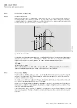
A single-phase fan, a blower or a convector can be controlled with the fan output. In combination
with valve control, 2- or 4-pipe systems can be implemented. The fans are controlled via a 3-stage
speed controller. For this purpose, three windings are tapped off the fan motor. The resulting fan
speed is dependent on the tapping selected. For control purposes, at least one 3-stage
changeover switch with zero position is usually used. For the switching function control type, it
must be ensured that two contacts are not switched on simultaneously. This switch is mapped with
a group of outputs in the device.
Fig. 61: Fan operation
2CDC072006F0118


