


FEP630, FEH630
ELECTROMAGNETIC FLOWMETER | OI/FEP630/FEH630-EN REV. D
17
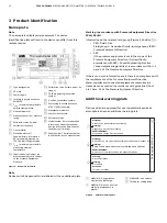
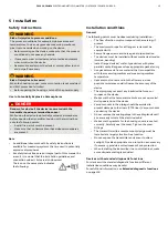
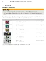
Electrode axis
1
Electrode axis
Figure 12: Orientation of the electrode axis
The flowmeter sensor should be mounted in the piping in such a
manner that the electrode axis is oriented as horizontally as
possible.
A maximum deviation of 45° from the horizontal position is
permissible.
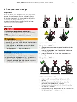
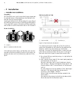
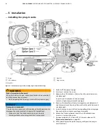
Mounting position
Figure 13: Mounting position
A
Vertical installation for measuring abrasive materials,
preferably with flow in upward direction.
B
For a horizontal installation, the meter tube must always be
completely filled with the measuring medium.
Provide for a slight incline of the connection for degassing.
Note
For hygienic applications, the vertical mounting position is
preferred.
For a horizontal mounting position, make sure that the sensor is
installed to be self-draining.
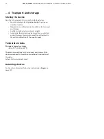
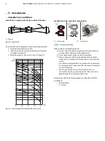
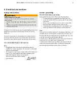
Minimum spacing of the devices
Spacing D:
≥
1.0 m (3.3 ft) for Design Level ‘A’,
≥
0.7 m (2.3 ft) for Design Level ‘B’
G12063
HygienicMaster
xxx
FEH
D
Spacing D:
≥
1.0 m (
≥
3.3 ft)
Figure 14: Minimum spacing
• In order to prevent the devices from interfering with each
other, a minimum distance as presented in
Minimum spacing
of the devices
must be maintained between the devices.
• The sensor must not be operated in the vicinity of powerful
electromagnetic fields, e.g., motors, pumps, transformers,
etc. A minimum spacing of approx. 1 m (3.28 ft) must be
maintained.
• For installation on or to steel parts (e.g. steel brackets), a
minimum spacing of 100 mm (3.94 in
)
must be maintained.
These values have been calculated on the basis of IEC 801-2
or IEC TC77B


